5 Installation
18
Installation and maintenance instructions ecoTEC plus 0020261188_00
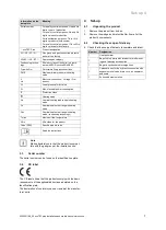
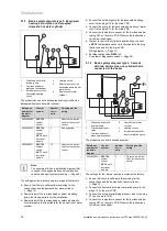
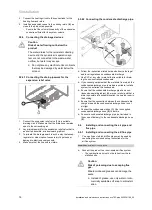
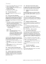
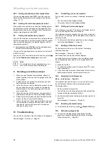
5.7.1.2 Closing the electronics box
1.
Close the cover by pushing it downwards onto the elec-
tronics box.
2.
Ensure that all of the clips audibly click into the retain-
ers.
3.
Tilt the electronics box upwards.
5.7.2
Carrying out the wiring
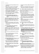
Caution.
Risk of material damage caused by incor-
rect installation.
Mains voltage at incorrect terminals and plug
terminals may destroy the electronics.
▶
Do not connect the eBUS terminals (+/
‑
)
to the mains voltage.
▶
Only connect the power supply cable to
the terminals marked for the purpose.
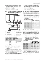
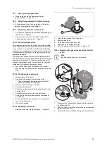
230V
24V / eBus
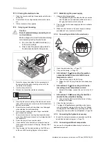
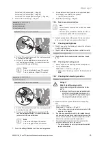
1
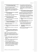
1.
Route the connection cables for the components to
be connected in the cable trunking on the left of the
underside of the product.
2.
Use the strain reliefs
(1)
.
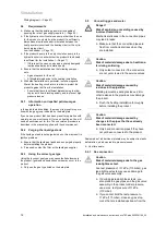
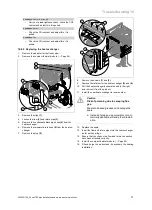
3.
Shorten the connection cables as necessary.
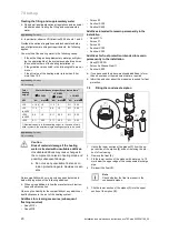
30 mm max.
4.
Only strip the outer sheathing of flexible lines to a max-
imum of 30 mm to prevent short circuits if a strand acci-
dentally comes loose.
5.
Ensure the inner conductor insulation is not damaged
when stripping the outer sheathing.
6.
Only strip inner conductors just enough to establish
good, sound connections.
7.
To avoid short circuits resulting from loose individual
wires, fit conductor end sleeves on the stripped ends of
the conductors.
8.
Screw the plug to the connection cable.
9.
Check whether all conductors are properly fastened
to the connection terminals of the plug. Remedy this if
necessary.
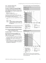
10. Plug the plug into the slot provided on the PCB in ac-
cordance with the wiring diagram in the appendix.
5.7.3
Establishing the power supply
1.
Observe all valid regulations.
–
The applicable regulations state that the connection
must be made via an electrical partition with a con-
tact gap of at least 3 mm at each pole.
2.
Plug the plug for the power supply cable into a suitable
plug socket.
3.
Make sure that access to the power supply is always
available and is not covered or blocked.
5.7.4
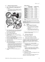
Connecting controls to the electronics
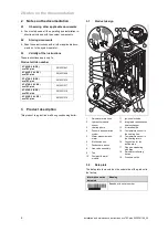
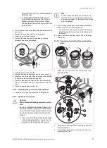
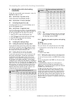
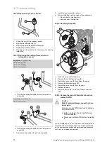
24V=
230V~
– +
24V=
RT
BUS
Burner
off
1.
Open the electronics box. (
→
Page 17)
2.
Carry out the wiring. (
→
Page 18)
3.
Alternatives 1 / 3
‒
Connecting the weather-
compensated
eBUS
control or
eBUS
room
temperature control:
▶
Connect the control to the
BUS
plug.
▶
Bridge the
24V=RT
plug if this has not already been
done.
3.
Alternatives 2 / 3
‒
Connecting a
24 V
extra-
low voltage room temperature control:
▶
Instead of the bridge, connect the control to the
24 V
plug.
3.
Alternatives 3 / 3
‒
Connecting the limit ther-
mostat for the underfloor heating:
▶
Connect the limit thermostat to the
Burner off
plug
instead of the bridge.
4.
Close the electronics box.
5.
To trigger the
Comfort
pump operating mode (pump
runs permanently) using a multi-circuit control, change
the diagnostics code
D.018
pump operating mode from
Eco
(pump runs intermittently) to
Comfort
. (
→
Page 26)
5.7.5
Connecting the hydraulic accessory
▶
Connect the hydraulic accessory in accordance with the
selected basic system diagram. (
→
Page 10)
5.7.6
Connecting additional components
You can use the integrated additional relay to actuate an
additional component.

