Inspection and maintenance 11
0020261188_00 ecoTEC plus Installation and maintenance instructions
35
6.
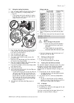
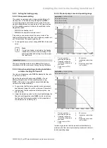
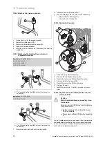
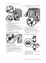
Remove the plugs
(1)
and
(2)
from the fan motor by
pushing in the latching lug.
7.
Remove the plug from the gas valve assembly
(3)
.
8.
Unscrew the four nuts
(6)
.
9.
Remove the fixing tab
(7)
for the air intake pipe.
10. Pull the assembly group for the compact thermal
module
(8)
out of the heat exchanger.
11. Check the burner and the heat exchanger for damage
and dirt.
12. If necessary, clean or replace the components accord-
ing to the following sections.
13. Fit a new burner flange seal.
14. Check the insulating mat on the back panel of the heat
exchanger.
–
If you notice any signs of damage, replace the insu-
lating mat.
15. Check the insulating material on the burner flange.
–
If you notice any signs of damage, replace the insu-
lating mat.
11.3.3 Cleaning the heat exchanger
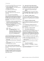
1
2
3
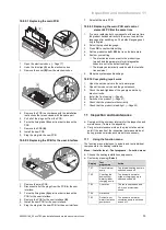
1.
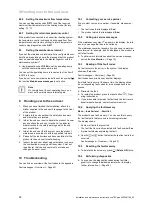
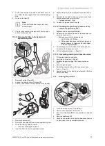
Never undo the four nuts on the threaded pin
(1)
or
tighten them.
2.
Clean the spiral immersion heater
(2)
of the heat ex-
changer using water or, if required, vinegar (up to a
maximum acid content of 5%). Allow the vinegar to act
on the heat exchanger for 20 minutes.
3.
Use a plastic brush or sufficiently strong jet of water to
remove the loosened dirt. In doing so, ensure that no
spraying water reaches the other components. Do not
point the jet of water directly at the insulating mat
(3)
on
the back of the heat exchanger.
◁
The water flows via the condensate siphon and out
of the heat exchanger.
4.
Check the insulating mat on the heat exchanger for
damage.
▽
Insulating mat is damaged:
▶
Replace the insulating mat.
11.3.4 Checking the burner
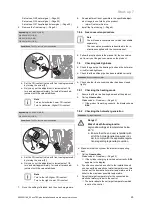
1
2
3
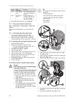
1.
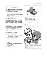
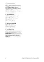
Check the surface of the burner
(1)
for damage. If you
see any damage, replace the burner.
2.
Check the burner's insulation
(2)
. If required, replace
the burner's insulation.
3.
Fit a new burner flange seal
(3)
.
11.3.5 Installing the compact thermal module
1
2
7
8
6
5
3
4
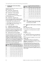
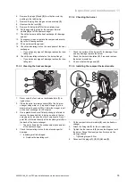
1.
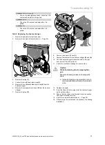
Fit the compact thermal module
(8)
onto the heat ex-
changer.
2.
Attach the fixing tab
(7)
for the air intake pipe.
3.
Tighten the four new nuts
(6)
across the diagonal until
the burner flange fits closely and uniformly onto the
mating surfaces.
–
Tightening torque: 6 Nm
4.
Reconnect the plugs
(1)
,
(2)
,
(3)
,
(4)
and
(5)
.

