Inspection and maintenance 11
0020261188_00 ecoTEC plus Installation and maintenance instructions
33
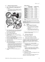
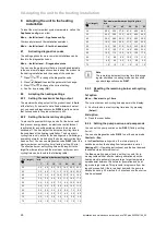
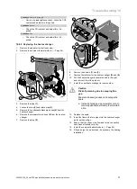
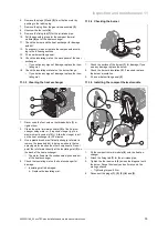
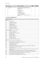
10.9.9.1 Replacing the main PCB
x 2
A
B
1.
Open the electronics box. (
→
Page 17)
2.
Undo the two clips
(A)
on the electronics box.
3.
Remove the cover
(B)
from the electronics box.
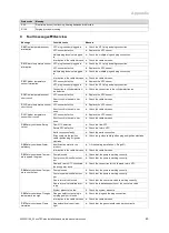
x 3
A
B
4.
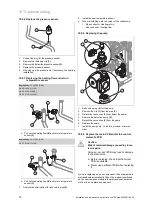
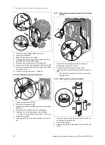
Remove the PCB in accordance with the installation
instructions that are enclosed with the spare part.
5.
Pull all of the plugs out from the PCB.
6.
Force the fixing tabs
(A)
apart in order to loosen the
PCB.
7.
Remove the PCB
(B)
.
8.
Install the new PCB.
9.
Plug the plug into the new PCB.
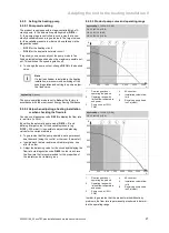
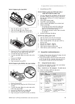
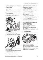
10.9.9.2 Replacing the PCB for the user interface
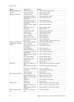
x 4
A
B
1.
Remove the main PCB.
2.
Disconnect all of the plugs from the PCB for the user
interface.
3.
Force the fixing tabs
(A)
apart in order to loosen the
PCB for the user interface.
4.
Remove the PCB for the user interface
(B)
.
5.
Install the new PCB for the user interface.
6.
Plug the plug into the new PCB for the user interface.
7.
Reinstall the main PCB.
10.9.9.3 Replacing the main PCB and control
element's PCB at the same time
1.
If you are replacing both components at the same time,
the product switches directly to the menu to select the
language after switching on. The default language set-
ting is English.
2.
Select the required language.
3.
Press
OK
to confirm this setting.
4.
Set the product code
D.093
that is on the data plate.
5.
Confirm your setting.
◁
The electronics are now set to the product type
(model) and the parameters for all diagnostics
codes are set to the default settings.
◁
The display automatically restarts with the installa-
tion assistant.
6.
Make the system-specific settings.
10.9.10 Completing repair work
1.
Open the service valve in the cold water pipe.
2.
Open all service valves and the gas stopcock.
3.
Check the leak-tightness of the gas pipe and the hy-
draulic circuits.
4.
Install the front casing. (
→
Page 9)
5.
Switch on the product. (
→
Page 21)
6.
Check that the product works correctly.
7.
Check that the product is leak-tight. (
→
Page 25)
11 Inspection and maintenance
▶
Comply with the minimum intervals for the inspection and
maintenance ( Table in the appendix).
▶
Carry out maintenance work on the product at an earlier
point if the results of the inspection that was carried out
during previous maintenance make this necessary.
11.1
Using the function menu
The function menu allows you to actuate and test individual
components in the heating installation.
Menu
→
Installer level
→
Test programs
→
Function menu
▶
Choose the heating installation components.
▶
Confirm by pressing (
Select
).
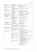
Display
Test
programme
Action
T.01
Check internal
pump
The internal heating pump is
switched on and off.
T.02
Checking the
domestic hot
water cylinder
charging pump
The domestic hot water
cylinder charging pump is
switched on and off.
T.03
Check fan
The fan is switched on and
off; it runs at maximum
speed.
T.04
Not active
T.05
Domestic hot
water circulation
pump check
The domestic hot water
circulation pump is switched
on and off.


