Adapting the unit to the heating installation 8
0020261188_00 ecoTEC plus Installation and maintenance instructions
27
8.2.5
Setting the heating pump
8.2.5.1 Pump mode setting
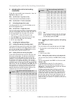
The product is equipped with a stage-controlled high-effi-
ciency pump. In the automatic operating mode (
D.014
=
0), the pump stage is controlled in such a way that a con-
stantly available pressure is guaranteed. The target values
for the available pressure in mbar can be called up via the
diagnostics codes:
–
D.122
for the heating circuit
–
D.148
for the domestic hot water circuit
If required, you can manually set the pump mode to five
fixed, selectable stages based on the maximum possible out-
put. This switches the speed regulation off.
▶
To change the pump output, change
D.014
to the desired
value.
Note
If a low loss header is installed in the heating
installation, we recommend switching off the
speed regulation and setting the pump output
to a fixed value.
Applicability:
Germany
The pump operating mode is set to
Auto
at the factory in
accordance with the most recent Energy Saving Ordinance.
8.2.5.2 Help when adjusting a heating installation
or when checking the flow rate
You can use diagnostics code
D.029
to display the flow rate
in real time (in l/min).
By setting the automatic pump mode (
D.014
= 0) and
defining a target value for the available pressure (e.g.
D.122
= 200 mbar), it is possible to adjust the balancing
valves for the various radiators.
▶
To guarantee that the pump operates, set a permanent
heat demand (using the control or the room thermostat).
▶
Insulate each radiator and/or each radiator group, one
after the other.
▶
Adjust the balancing valve for the circuit by displaying the
flow rate via diagnostics code
D.029
in order to achieve
the flow rate that is recommended for the properties of
the radiator and/or radiator group.
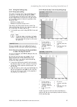
8.2.5.3 Product pump curve and operating range
Applicability:
VC 406/5-5 (E-DE)
OR VC 406/5-5 (LL-DE)
OR VC 476/5-5 (E-DE)
OR VC 476/5-5 (LL-DE)
600
800
1000
400
200
0
500
1000
1500
2000
A
B
2500
3000
3
4
1
2
1
Flow range without
operating the product
2
Operating range with
limited flow temperature
and power
3
Pump curve at 100%
PWM
4
Δ
P constant
A
Installation volume flow
in l/h
B
Remaining pump head
in hPa (mbar)
Applicability:
VC 636/5-5 (E-DE)
OR VC 636/5-5 (LL-DE)
600
800
1000
1200
400
200
0
500
1000
1500
2000
A
B
2500
3000
3500
3
4
1
2
1
Flow range without
operating the product
2
Operating range with
limited flow temperature
and power
3
Pump curve at 100%
PWM
4
Δ
P constant
A
Installation volume flow
in l/h
B
Remaining pump head
in hPa (mbar)
In order to guarantee that the product works without any
problems, the flow rate is permanently monitored to determ-
ine the operating range.

