background image

Chapter 5: Technical specifications 

84 

ZP1-X3E Series Installation Manual 

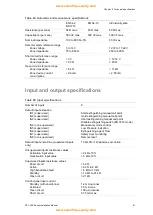
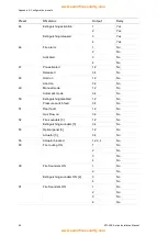
Table 30: Expansion board current consumption

 [1]


Number of expansion boards 

Up to 4 

2010-1-SB output specifications 
 

Number of outputs 


Output type 


Output inactive 


Output active 


Current rating (when active) 


Current consumption (standby) 


Internal power mode current rating 


External power mode current rating 

 
4 (OUT1 to OUT4) 
24 VDC supervised output 

−10 to −13 VDC (reverse polarity supervision) 
21 to 28 VDC (24 VDC nominal) 
250 mA max. 
15 mA at 24 VDC 
300 mA max for all expansion boards 
1 A max per expansion board 

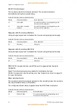
2010-1-RB output specifications 
 

Number of outputs 


Output type 


Number of potential-free contacts 


Current rating (when active) 


Current consumption (standby) 


Current consumption (active) 

 
4 (OUT1 to OUT4) 
Free-of-voltage relay 
2 (normally-open NO and normally-closed NC) 
2 A max. at 30 VDC 
15 mA at 24 VDC 
50 mA (all outputs) at 24 VDC 

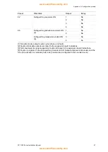
[1] Optional expansion board not supplied with control panel. 

Table 31: Power supply equipment specifications for EN 54-4 

Current consumption (Imin) [1] 

0.05 A min. 

Current consumption in standby (Imin a) 

0.39 A max. 

Current consumption in alarm (Imax b) 

2.78 A max. 

[1] All zones and inputs in standby, no outputs activated, no expansion boards installed, no 24V 
auxiliary used and batteries fully charged. 

Mechanical and environmental specifications 

Table 32: Mechanical specifications 

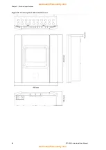
Cabinet dimensions without cover 

421 × 100 × 447 mm 

Weight without batteries  

3.9 kg 

Number of cable knockouts 

20 x Ø 20 mm at top of cabinet 
2 x Ø 20 mm at bottom of cabinet 
26 x Ø 20 mm at rear of cabinet 

IP rating 

IP30 

Table 33: Environmental specifications 

Environmental class 

Class A 

Operating temperature 
Storage temperature 

−5 to +40ºC 

−20 to +70ºC 

Relative humidity 

10 to 95% noncondensing 

Type class conditions 

3K5 of IEC 60721-3-3 


www.acornfiresecurity.com

www.acornfiresecurity.com

Содержание ZP1-X3E Series

Страница 1: ...ZP1 X3E Series Installation Manual www acornfiresecurity com www acornfiresecurity com ...

Страница 2: ...lska Sp Z o o Ul Kolejowa 24 39 100 Ropczyce Poland Authorized EU manufacturing representative UTC Fire Security B V Kelvinstraat 7 6003 DH Weert Netherlands Version This document covers control panels with firmware version 2 0 or later Certification European Union directives 1999 5 EC R TTE directive Hereby UTC Fire Security declares that this device is in compliance with the essential requiremen...

Страница 3: ...guration 60 Fire network and repeaters configuration 62 Commissioning 70 Chapter 4 Maintenance 75 System maintenance 76 Battery maintenance 77 Chapter 5 Technical specifications 79 Zone specifications 80 Input and output specifications 81 Power supply specifications 83 Mechanical and environmental specifications 84 Appendix A Configuration presets 87 Input and output configuration 88 Default delay...

Страница 4: ...ages advise you of possible equipment damage They tell you which actions to take or to avoid in order to prevent the damage Note Note messages advise you of the possible loss of time or effort They describe how to avoid the loss Notes are also used to point out important information that you should read Limitation of liability To the maximum extent permitted by applicable law in no event will UTCF...

Страница 5: ...des and the instructions of the authority having jurisdiction is mandatory While every precaution has been taken during the preparation of this manual to ensure the accuracy of its contents UTCFS assumes no responsibility for errors or omissions www acornfiresecurity com www acornfiresecurity com ...

Страница 6: ...iv ZP1 X3E Series Installation Manual www acornfiresecurity com www acornfiresecurity com ...

Страница 7: ...er 1 Introduction Summary This chapter provides an introduction to your control panel and the available operating modes Content Product description 2 Product compatibility 2 Operating modes 2 www acornfiresecurity com www acornfiresecurity com ...

Страница 8: ... with products that are not listed in that document cannot be guaranteed For further details contact your local supplier Note The CleanMe self diagnostics feature listed in selected presets is not available for ZP1 X3E Series devices Operating modes Supported operating modes are shown in the table below The default operating mode is EN 54 2 with EN 54 13 supervision disabled Table 1 Operating mode...

Страница 9: ...ng national standard and any other applicable regulations Content Control panel cabinet layout 4 Cabinet installation 5 Preparing the cabinet 5 Where to install the cabinet 5 Fixing the cabinet to the wall 5 Connections 7 Recommended cables 7 Connecting zones with initiating devices 7 Connecting inputs 10 Connecting outputs 14 Connecting the mains power supply 17 Connecting the batteries 18 Connec...

Страница 10: ...ery area 7 Power supply unit 8 Key connector see note 9 Fuse terminal block 10 Power supply connector 11 Battery connector 12 Expansion board connector 13 Cable holder Note The control panel is available with a key option The key switch is located on the panel cover With this option either the key or the password can be used to enter the operator user level This key can also be configured to be us...

Страница 11: ...ironmental specifications on page 84 for more information on the operating temperature and relative humidity specifications Allow for enough floor and wall space so the panel can be installed and serviced without any obstructions The cabinet should be mounted so that the user interface is at eye level Note that the control panel must be assembled and installed according to the ordinances and codes...

Страница 12: ... points on the wall using the cabinet as a template 2 Drill all required holes and insert a 6 mm wall plug into each 3 Insert a screw in position 1 and hang the cabinet onto this screw 4 Insert screws in positions 2 and tighten 5 Insert screws in position 3 and tighten 6 Tighten screw in position 1 www acornfiresecurity com www acornfiresecurity com ...

Страница 13: ...pes of cable may be used subject to site specific EMI conditions and installation testing Use 20 mm cable glands to ensure clean and secure connections at the control panel cabinet All cables should be fed through the cable guides in the cabinet housing to eliminate movement Connecting zones with initiating devices Zone configuration The control panel has three fire detection zone inputs marked Z1...

Страница 14: ...ues Zone type EN 54 2 BS 7273 EN 54 13 Intrinsically safe Mixed detection 40 Ω max Not supported 1 Not supported 1 Automatic detection 55 Ω max 50 Ω max 50 Ω max Manual detection 55 Ω max 50 Ω max 50 Ω max 1 Mixed zones are not permitted in installations requiring EN 54 13 or intrinsically safe configurations To measure the line resistance 1 Disconnect all zone devices 2 Create a short circuit at ...

Страница 15: ...echnical specifications on page 79 Note For BS 7273 installations a diode must be connected on the detector base see your detector installation manual for more details Connecting fire alarm manual call points Connect fire alarm manual call points in parallel Each fire zone can support a maximum of 32 manual call points In zones used for fire detection manual call points must have a resistance inst...

Страница 16: ...ch BS 7273 mode Supervised IN4 Manual only mode activation device Unsupervised IN5 Low pressure indication Supervised IN6 Extinguishing agent flow Supervised IN7 Safety door fault monitoring Supervised IN8 Remote reset Unsupervised Input termination Only supervised inputs require a 15 kΩ 5 1 4 W end of line resistor for termination If a supervised input is not used the end of line resistor must be...

Страница 17: ...olds the extinguishing process When the panel is in the extinguishing activation state the actuator output is not activated while the MCP Hold device is activated continuously The MCP Hold input can be configured for two different operating modes Mode A and Mode B Table 7 MCP Hold operating modes Mode Description Mode A When the MCP Hold is activated the actuator delay countdown continues but the ...

Страница 18: ...igure the system by setting the Manual only mode local option to OFF Note EU ordinances and regulations require the use of a key switch to control access to this function See Input and output specifications on page 81 for the required impedance values for this unsupervised input Connecting a low pressure indication switch Use the low pressure indication input to detect low pressure in the extingui...

Страница 19: ... fault prevents the panel from entering the extinguishing activation state because of life safety issues and activating the actuator to ensure property protection When the panel is in manual only mode the safety door must be open A closed door signal is interpreted as a fault When the panel is in manual automatic mode the safety door must be closed An open door signal is interpreted as a fault You...

Страница 20: ...below Table 8 Output functionality Output Function Type and status OUT1 Hold extinguishing manual call point Free of voltage unsupervised switch Hold inactive open Hold active closed OUT2 Abort extinguishing manual call point Disable extinguishing switch BS 7273 mode Free of voltage unsupervised switch Abort inactive open Abort active closed Free of voltage unsupervised switch Enabled open Disable...

Страница 21: ...open NO and the common C terminals of a relay to provide the free of voltage isolated unsupervised switch functionality When the output is in standby the NO and C terminals are open When the output activates the relay changes to close the NO and C terminals The maximum rating per active output is 2 A at 30 VDC Figure 5 Control panel free of voltage outputs 1 Switch terminal NO 2 Switch terminal C ...

Страница 22: ...Observe polarity or install a 1N4007 diode or equivalent to avoid inverted activation issues Connecting the extinguishing actuator output Note Observe the polarity of the extinguishing actuator output to ensure proper operation WARNING Risk of death or serious injury Test the line supervision for open and short circuit faults and the activation function before connecting the extinguishing agent to...

Страница 23: ... building electrical supply distribution board This circuit should be clearly marked have a bipolar disconnect device and only be used for fire detection equipment Feed all mains cables through the appropriate cable knockouts and connect them to the fuse terminal block as shown in Figure 8 below Keep mains cables separate from other cabling to avoid potential short circuits and interference Always...

Страница 24: ...on Risk of equipment damage An incorrect power setting can destroy the power supply Figure 9 Selecting 115 or 230 VAC operation Connecting the batteries The control panel requires two 12 V 7 2 or 12 Ah rechargeable sealed lead acid batteries Batteries must be installed in series at the base of the control panel cabinet Use the battery lead and bridge provided and connect batteries to the BATT conn...

Страница 25: ...tput as shown in Figure 11 below The 24 VDC auxiliary output is supervised for short circuit and voltage output Figure 11 Auxiliary power supply output connection 24VAUX 1 External equipment to be powered with 24 VDC See Table 28 on page 83 for the maximum current and other output ratings Caution Never use the auxiliary output to power expansion boards connected to the same control panel as this m...

Страница 26: ...rm relay output connections 1 Normally open contact 2 Normally closed contact 3 Common Connecting expansion boards Caution Risk of equipment damage Always disconnect the control panel from the mains power supply before installing an expansion board See your expansion board installation sheet for detailed installation information Connecting a fire network Note See the 2010 1 NB Network Board Instal...

Страница 27: ...own below Figure 14 Fire network ring configuration Bus configuration Note To be compliant with EU regulations use this network configuration only in cases where the detection zones and mandatory EN 54 2 output functions sounder and fire routing outputs are not remote between panels Bus network configuration is not normally recommended as it does not provide for redundancy in the transmission path...

Страница 28: ...Chapter 2 Installation 22 ZP1 X3E Series Installation Manual www acornfiresecurity com www acornfiresecurity com ...

Страница 29: ...ire delay operation 36 Adding expansion boards 37 Advanced configuration 37 The advanced configuration menu 37 Safety door monitoring 42 Safety door fault delay 42 Pressure switch type 43 Hold mode 43 Activation tone 44 Released tone 44 Extinguishing zones 45 Manual only mode local 46 Manual key mode 47 Enable flooding time 48 Flooding time 49 Actuator delay for start manual call point 50 Extingui...

Страница 30: ...board 60 Expansion board configuration 60 Fire network and repeaters configuration 62 Basic configuration options 62 Advanced configuration options 65 Commissioning 70 Before commissioning the control panel 70 Commissioning the control panel 71 Functional tests 72 Response times 73 www acornfiresecurity com www acornfiresecurity com ...

Страница 31: ...isabled LED 14 General Disable button and LED 15 General Test button and LED 16 Low Pressure LEDs 17 Extinguishing Agent Flow LEDs 18 Reset button and LED 19 Panel Silence button and LED 20 Fire Sounders Start Stop button and LED 21 Numeric keypad and Enter button 22 Manual Mode button and LED 23 System Fault LED 24 Out of Service LED 25 Earth Fault LED 26 Supply Fault LED 27 MCP Abort LEDs 28 MCP...

Страница 32: ... public user level is the default user level This level allows basic operating tasks such as responding to fire alarms extinguishing events or fault warnings at the control panel No password is required Operator user The operator user level allows additional operating tasks that command the system or perform maintenance functions It is reserved for authorized users who have been trained to operate...

Страница 33: ...ration options to set a custom zone delay zone configuration or zone type then the seven segment display defaults to the custom display operating mode See Panel mode on page 33 Configuration overview To facilitate rapid configuration of the most common tasks configuration is divided into basic and advanced levels For basic configuration options see Basic configuration on page 31 For advanced confi...

Страница 34: ...y Enter Confirm a menu selection or a value selection entry Note The configuration controls are also used to enter the user level password The seven segment display The seven segment display is only visible when the control panel cover is removed see Figure 1 on page 4 Figure 18 The seven segment display 1 Mode LED 2 Value LED Table 11 Mode and value LEDs LED Indications Mode Select a configuratio...

Страница 35: ...ion buttons 1 and 3 2 Press Enter When a configuration menu has been selected the Value LED on the seven segment display is steady To select a value 1 Select the required value using the value selection buttons 2 and 4 2 Press Enter To exit configuration mode and save your changes 1 Press Panel Silence 2 Press Enter or 1 Set the display as shown below and then press Enter The Panel Silence LED fla...

Страница 36: ...s Table 12 Visible indications for values Status Indication Current value Both decimal points on the display are steady New selected value Both decimal points on the display are flashing Other value Both decimal points on the display are off To restore the previous configuration 1 Set the display as shown below and then press Enter To restore the factory configuration 1 Set the display as shown be...

Страница 37: ...nu Values Basic default configuration 01 02 05 06 11 12 13 14 61 63 EN 54 13 supervision Of EN54 13 supervision Off and class B outputs A EN54 13 supervision On for zone and class A expansion board outputs Default Off Panel mode Basic standard Basic evacuation BS 7273 mode stage 1 BS 7273 mode stage 2 Repeater with fire routing EN 54 2 Repeater with fire routing BS 7273 Custom Actuator delay 00 to...

Страница 38: ...e shown in the table below The default setting is 01 Basic standard mode passive end of line Table 14 Operating mode configuration presets Display Mode Zone configuration Manual fire sounder start Actuator delay for MCP Start 01 default Basic standard Passive end of line No Yes 02 Basic standard Passive end of line CleanMe enabled No Yes 05 Basic evacuation Passive end of line Yes operator user le...

Страница 39: ...ast to indicate that the supervision mode is active 3 Press Enter 4 Save your changes The available settings for this feature are shown below Display Description EN 54 13 supervision On for zone and class A expansion board outputs Standard zone supervision with class B fire outputs default Note This menu is not visible if the panel operational mode is BS 7273 either stage 1 or stage 2 or includes ...

Страница 40: ...outing functionality can be repeated Repeater with fire routing BS 7273 Fire routing functionality can be repeated Custom A custom operating mode is configured The display alternates between CU custom and the operation mode Note In basic evacuation operating mode the configured actuator delay is bypassed when MCP Start is activated The actuator output is activated immediately Custom panel operatin...

Страница 41: ...igure a reset disabled delay of up to 30 minutes in steps of 1 minute The default setting is for a 2 minute delay To configure a reset disabled delay 1 Set the display as shown below and then press Enter 2 Select a delay value from 00 to 30 minutes using the value selection buttons 2 and 4 3 Press Enter 4 Save your changes Fire sounders delay Use this menu to configure a fire sounders delay of up ...

Страница 42: ...ration see Fire delay operation below To configure a delay 1 Set the display as shown below and then press Enter The Fire Routing Delay LED flashes fast to indicate that the fire routing delay configuration menu is active 2 Select a delay value from 00 to 10 minutes using the value selection buttons 2 and 4 3 Press Enter 4 Save your changes Once configured the delay must be enabled at the operator...

Страница 43: ... See the expansion board s installation guide for installation instructions See Expansion board configuration on page 60 for configuration instructions Advanced configuration The default password for advanced configuration is 4444 After entering the password the first displayed menu is the Advanced default configuration indicating advanced installer user level For more information see User level p...

Страница 44: ... switch type Normally closed Normally open Default Normally closed Activation tone Pulsed Continuous Default Pulsed Released tone Pulsed Continuous Default Continuous Extinguishing zones Z1 extinguishing Z2 and Z3 fire Z1 and Z2 extinguishing Z3 fire Z1 Z2 and Z3 extinguishing No extinguishing zones Z1 Z2 Z3 fire Default Z1 Z2 extinguishing Z3 fire Manual only mode local ON OFF Default On Hold mod...

Страница 45: ...er 0 to 32 0 Stand alone no networking Default 0 Firenet group Allows you to configure the panel to work in a 32 node network or in a group of 32 nodes inside a 250 node network 0000 0250 0000 to 0218 Default 0000 The number has four digits Identified by position these are 1234 Press Up to enter the first two digits of the number positions 1 and 2 Press Down to enter the last two digits of the num...

Страница 46: ...F Default On Firenet map 01 to 32 ON OFF On for nodes 1 and 2 Off for the rest Firenet repeater map 01 to 32 ON OFF On for nodes 1 and 2 Off for the rest Firenet analogue repeater remote node ON OFF Default Off Firenet remote output control ON OFF Default Off Extinguishing Firenet global controls ON OFF Default Off Software version Read only Configuration version Read only Configuration time stamp...

Страница 47: ...el password 0 to 4444 Default 4444 Control panel PCB serial number Read only Auxiliary 24V reset ON OFF Default Off Restore previous configuration N A Restore factory configuration N A Exit without saving N A Exit and save N A Note See Basic configuration on page 31 for details on the settings available in basic configuration Panel mode Actuator delay Reset disabled delay Fire sounders delay and F...

Страница 48: ...ess Enter 4 Save your changes The available settings for this feature are shown below Display Description Safety door monitoring is used on Safety door monitoring is not used off Safety door fault delay Use this menu to configure a delay from 10 to 90 seconds in steps of 5 seconds in reporting safety door faults caused by incorrect status open or closed The default setting is 30 seconds To configu...

Страница 49: ...nd 4 3 Press Enter 4 Save your changes The available settings for this feature are shown below Display Description Operates as normally closed NC Operates as normally open NO Hold mode Use this menu to set the operating mode for this device mode A or B The default setting is mode A For a description of the emergency MCP Hold function and device see Connecting extinguishing system manual call point...

Страница 50: ...rn is 1 second on 1 second off The default setting is pulsed mode To configure the activation tone 1 Set the display as shown below and then press Enter The red Extinguishing Sounders LED flashes fast to indicate that the configuration menu is active 2 Select a value using the value selection buttons 2 and 4 3 Press Enter 4 Save your changes The available settings for this feature are shown below ...

Страница 51: ...ishing area are assigned standard fire detection functionality The configuration options available are shown in the table below Table 16 Extinguishing zone options Option Zones Description 1 Z1 An alarm in Z1 initiates the extinguishing event The control panel provides standard fire detection for Z2 and Z3 both as mixed zones 2 Z1 and Z2 default Both Z1 and Z2 must be in alarm to initiate an extin...

Страница 52: ... are configured as fire detection zones Manual only mode local When the control panel is in manual only mode the extinguishing process can only be initiated manually using the MCP Start device Automatic extinguishing events reported from the fire detection zones are disabled for extinguishing activation The panel can be switched to manual only mode using two methods by pressing the Manual Mode but...

Страница 53: ...Display Description Manual only mode is set locally Manual only mode is activated by the Manual Mode button on the panel Manual only mode is set remotely Manual only mode is activated by the manual only mode activation device Manual key mode Use this menu to configure the manual key functionality if your control panel has a key switch installed in the door The default setting is off To configure t...

Страница 54: ...is the key is inserted and turned the panel will stay in manual mode independently of the operator level auto manual button actions on the keypad and related network commands If the key position is OFF that is the key is not inserted or is inserted but not turned the panel accepts an operator level request to change the auto manual using the button or the related network commands Enable flooding t...

Страница 55: ...value is 0 min 0 sec The maximum value is 5 min If the flooding time is set to 0 min 0sec the flooding time enable will be set to OFF To configure the flooding time 1 Set the display as shown below and then press Enter The red Released LED flashes fast to indicate that the configuration menu is active and nn minutes and SS seconds appears 2 Select a value using the value selection buttons 2 and 4 ...

Страница 56: ...ess Enter 4 Save your changes The available settings for this feature are shown below Display Description Actuator delay applies to the MCP Start MCP Start activates the actuator immediately no delay Extinguishing agent flow Use this menu to configure how the control panel enters into the extinguishing released state using extinguishing agent flow confirmation or immediately after the activation o...

Страница 57: ...ation purposes Fire sounder operation during a zone test Use this menu to configure the sounder operation during a zone test The default setting for all operating modes is On To configure the sounder operation during a zone test 1 Set the display as shown below and then press Enter The Fire Sounders Start Stop LED flashes fast to indicate that the sounder operation during a zone test configuration...

Страница 58: ...nd if a new fire alarm event is reported from a different zone Fire sounders silence disabled time Note For control panels in basic evacuation mode any configured fire sounders silence disable times are ignored To prevent the immediate silencing of fire sounders when a fire alarm is first reported the Fire Sounder Start Stop button may be temporarily disabled for a preconfigured period of time whe...

Страница 59: ... 00 to 10 minutes using the value selection buttons 2 and 4 3 Press Enter 4 Save your changes Battery fault check Use this menu to configure the battery fault check on or off This determines whether the battery fault is supervised or not The default setting is On Note If disabled it does not comply with EN 54 2 and EN 54 4 To configure the battery fault check 1 Set the display as shown below and t...

Страница 60: ... a value using the value selection buttons 2 and 4 3 Press Enter 4 Save your change The available settings for this feature are shown below Display Description The earth fault check is enabled The earth fault check is disabled Fault latch Use this menu to configure the fault latch on or off This determines whether the power supply fault is latched or not The default setting is On To configure the ...

Страница 61: ...display as shown below and then press Enter 2 Select the zone for example zone 1 and then press Enter The red Zone LED flashes fast to indicate that the corresponding zone configuration menu is active 3 Select a value using the value selection buttons 2 and 4 4 Press Enter 5 Save your changes The available settings for this feature are shown below Display Description Passive end of line Active end...

Страница 62: ...1 and then press Enter The Zone alarm LED flashes fast to indicate that the corresponding zone configuration menu is active 3 Select a value using the value selection buttons 2 and 4 4 Press Enter 5 Save your changes The available settings for this feature are shown below Display Description Configured delays are allowed in the corresponding zone Configured delays are not allowed in the correspond...

Страница 63: ...0 Ω resistor This option is not available to zones configured in the extinguishing area Automatic zone All fire alarms are treated as reported by a detector even if the fire alarm is reported by a manual call point in the zone This is the option applied for zones configured in the extinguishing area Manual zone All fire alarms are treated as reported by a manual call point even if the fire alarm i...

Страница 64: ...er 2 Set the display as shown below and then press Enter 3 Select a value using the value selection buttons 2 and 4 4 Press Enter 5 Save your changes Auxiliary 24 V reset Use this menu to configure the auxiliary 24 V reset setting on or off The default setting is OFF To configure the 24 V reset 1 Set the display as shown below and then press Enter 2 Select a value using the value selection buttons...

Страница 65: ... boards you can also see the software version and PCB serial number These details may be required for troubleshooting and technical support Software version Configuration version Configuration time stamp Configuration date stamp Control panel PCB serial number The software version and control panel PCB serial number menus display a submenu that lets you select the object of interest Fire panel Mod...

Страница 66: ... Expansion board labels For configuration purposes expansion boards are labeled A B C and D The label for a given module is defined by its position left to right in the control panel cabinet The first expansion board installed is module A the second B etc See your expansion board installation sheet for installation instructions Expansion board function and delay configuration Once an expansion boa...

Страница 67: ...the expansion board flashes fast to indicate that the module function configuration menu is active 2 Select a value from 01 to 96 using the value selection buttons 2 and 4 3 Press Enter 4 Save your changes Expansion board output delay Use this menu to configure an expansion board output delay of up to 10 minutes where the feature is available To configure an expansion board output delay 1 For outp...

Страница 68: ...n a conventional panel is connected to a fire network it normally displays the status of one or more panels in the network depending on repeater configuration settings To display information for only that panel press the Enter key for 3 seconds to provide a temporary 30 second display of the local status indications Basic configuration options The following table shows the options for creating bas...

Страница 69: ...as an advanced custom pattern of node numbers the displayed value for the number of nodes is Cu A basic fire network is either a panel and a repeater or a six zone virtual panel composed of two three zone panels To configure a basic fire network 1 Activate networking by selecting the Firenet identifier node number in the fire network The value changes from 0 to 1 for a control panel and from 0 to ...

Страница 70: ...s setting can be used to configure control panels to repeat the status of control panels in the fire network with the zone LEDs Consult fire network advanced configuration settings for further details Basic fire network configuration will have the default fire network settings or the ones previously configured in the advanced fire network configuration options Default fire network settings are as ...

Страница 71: ... 19 Advanced configuration options for the fire network Display Description Value Firenet identifier 0 to 32 0 Stand alone no networking Default 0 Firenet group Allows you to configure the panel to work in a 32 node network or in a group of 32 nodes inside a 250 node network 0000 to 0218 Default 0000 The number has four digits Identified by position these are 1234 Press Up to enter the first two d...

Страница 72: ...nguishing global controls ON OFF Default Off 1 The basic configuration setting can be replaced by a customized set of specific panels for communication called a Firenet map and a set of panels to be repeated called a Firenet repeater map If the configuration is changed by modifying either map the value displayed for Firenet number of nodes is Cu indicating a custom network configuration Firenet gl...

Страница 73: ...s where alarm indications have to be local to the panel nP should be inactive By default process remote zone alarms is On Firenet and Firenet repeater maps If the control panels in the system do not have all the node IDs numbered consecutively starting from 1 or if the control panels do not repeat information from all other panels then configure Firenet map and Firenet repeater map Firenet map con...

Страница 74: ...ing repeated If control panels show different status the control panel with higher priority takes precedence if control panel 1 has sounders on delay and control panel 2 sounders on the indication of a third panel repeater will show sounders on All indications received that are not available in the repeater panel for display will be ignored Examples A conventional repeater panel can repeat an anal...

Страница 75: ... longer activate outputs based on its own logic and will only activate outputs with commands coming from the fire network This mode of operation is fail safe if the control panel detects a fire network fault the outputs will activate with the local logic or the remote commands By default Firenet remote output control is off for standalone applications or pure conventional fire networks where the c...

Страница 76: ...d in Terminating zones on page 8 All extinguishing devices with special attention to the extinguishing actuator are properly installed as described in Connections on page 7 Ensure that the polarity is correct and that the correct end of line is fitted if it is required Note Observe the polarity of the extinguishing actuator output to ensure proper operation WARNING Risk of death or severe injury T...

Страница 77: ...ators are on check your installation thoroughly before proceeding Fault startup In accordance with EN 54 2 the control panel has a special startup sequence that is used after an internal fault has been detected by the control panel This is indicated as follows The general Fault LED flashes fast The System Fault LED flashes slow When this happens 1 Enter the operator user level password 2 Press the...

Страница 78: ...ivate a fire detector to test automatic alarm reporting The control panel should initiate any configured delays and activate alarm notification devices and fire routing where applicable once the delay time has elapsed Verify the extinguishing functionality without connecting the extinguishing agent to the actuator Test these functions Manual MCP Start and automatic extinguishing zone detectors ext...

Страница 79: ...ss than 2 seconds MCP Abort fault Less than 2 seconds Other input faults Less than 3 seconds Actuator fault Less than 30 seconds Optical panel fault Less than 30 seconds Zone fault Less than 30 seconds Sounder fault Less than 30 seconds Fire routing fault Less than 30 seconds Earth fault Less than 100 seconds Battery charger fault Less than 100 seconds No batteries found fault Less than 3 minutes ...

Страница 80: ...Chapter 3 Configuration and commissioning 74 ZP1 X3E Series Installation Manual www acornfiresecurity com www acornfiresecurity com ...

Страница 81: ...ary This chapter includes information on system maintenance and battery maintenance Content System maintenance 76 Quarterly maintenance 76 Annual maintenance 76 Cleaning the control panel 76 Battery maintenance 77 www acornfiresecurity com www acornfiresecurity com ...

Страница 82: ...uarterly maintenance Test at least one device per zone and verify that the control panel responds to all fault and alarm events The control panel power supply and battery voltage should be checked Annual maintenance Test all system devices and verify that the control panel responds to all fault and alarm events All electrical connections must be visually inspected to make sure that they are secure...

Страница 83: ...connected securely and correctly at the battery and at the control panel PCB If the cables are in good condition and all connections are correct then the batteries should be replaced immediately Replacing batteries Batteries must be replaced periodically as recommended by the battery manufacturer The useful life of the battery is approximately four years Avoid the total discharge of the batteries ...

Страница 84: ...Chapter 4 Maintenance 78 ZP1 X3E Series Installation Manual www acornfiresecurity com www acornfiresecurity com ...

Страница 85: ... Summary This chapter includes technical specifications for your control panel Content Zone specifications 80 Input and output specifications 81 Power supply specifications 83 Mechanical and environmental specifications 84 www acornfiresecurity com www acornfiresecurity com ...

Страница 86: ...3 mode Number of detectors per zone Aritech Dx700 series Other detectors 20 max 32 max 1 2 Number of manual call points per zone 32 max 1 1 Or as defined by local standards 2 Provided that the detectors meet the required zone specifications given here Table 23 Mixed zone specifications Resistance per zone 40 Ω max Capacitance per zone 500 nF max Nominal impedance Detector Manual call point 160 to ...

Страница 87: ...upervised IN2 supervised IN3 supervised IN4 non supervised IN5 supervised IN6 supervised IN7 supervised IN8 non supervised Start extinguishing manual call point Hold extinguishing manual call point Abort extinguishing manual call point Disable extinguishing switch BS 7273 mode Manual only mode control Low Pressure indication Extinguishing Agent Flow Safety door monitoring Remote reset Default inpu...

Страница 88: ...tive Current rating when switch on 4 OUT1 to OUT4 Free of voltage switch galvanic isolated open circuit short circuit 2 A max at 30 VDC Standard supervised outputs Number of outputs Output type Output inactive Output active Current rating when active Start up current rating 3 OUT5 to OUT7 24 VDC supervised output 10 to 13 VDC reverse polarity supervision 21 to 28 VDC 24 VDC nominal 500 mA max at 2...

Страница 89: ...cations Operating voltage 110 VAC 60 Hz or 240 VAC 50 Hz Rated current 110 VAC 240 VAC 3 15 A 1 5 A Voltage tolerance 10 15 Mains fuse 110 VAC 240 VAC T 3 15A 250V T 2A 250V Table 28 24 VDC power supply specifications DC voltage 24 V Rated current 4 A Current range 0 to 4 A Rated power 100 W Voltage tolerance 2 Table 29 Batteries and battery charger specifications Batteries 2 7 2 Ah or 2 12 Ah Bat...

Страница 90: ... closed NC 2 A max at 30 VDC 15 mA at 24 VDC 50 mA all outputs at 24 VDC 1 Optional expansion board not supplied with control panel Table 31 Power supply equipment specifications for EN 54 4 Current consumption Imin 1 0 05 A min Current consumption in standby Imin a 0 39 A max Current consumption in alarm Imax b 2 78 A max 1 All zones and inputs in standby no outputs activated no expansion boards ...

Страница 91: ...Chapter 5 Technical specifications ZP1 X3E Series Installation Manual 85 Figure 20 Control panel cabinet without cover www acornfiresecurity com www acornfiresecurity com ...

Страница 92: ...Chapter 5 Technical specifications 86 ZP1 X3E Series Installation Manual Figure 21 Control panel cabinet with cover www acornfiresecurity com www acornfiresecurity com ...

Страница 93: ...s Content Input and output configuration 88 Default delays 88 Basic configuration modes 89 EN 54 2 supervision and Class B fire outputs 89 EN 54 13 supervision and Class A expansion board outputs 90 Expansion board functions 91 EN 54 2 supervision and Class B outputs 91 EN 54 13 supervision and Class A expansion board outputs 94 www acornfiresecurity com www acornfiresecurity com ...

Страница 94: ...Hold MCP Unsupervised OUT2 Abort MCP Disable extinguishing switch BS 7273 mode Unsupervised Unsupervised OUT3 Manual only mode Unsupervised OUT4 Extinguishing released Unsupervised OUT5 Fire sounders Supervised OUT6 Extinguishing sounders Supervised OUT7 Extinguishing released optical warning panels or signs Supervised OUT8 Actuator Supervised Default delays Table 35 Default delay configuration Fi...

Страница 95: ...nguishing event Z3 mixed for fire detection Basic evacuation mode Fire sounders can be manually activated at the operator user level in this operating mode a fire alarm is not required The actuator is activated immediately when the MCP Start is activated Table 37 Presets and zone characteristics Preset Zone description Zone detection 05 Passive EOL Z1 and Z2 automatic for extinguishing event Z3 mi...

Страница 96: ...t used Repeater with fire routing BS 7273 All input output supervision is disabled No fire and extinguishing functionality Table 41 Presets and zone characteristics Preset Zone description Zone detection 63 Not used Not used EN 54 13 supervision and Class A expansion board outputs Note The following presets are available for installations that use EN 54 13 supervision the SU setting is A See Super...

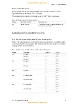
Страница 97: ...ire detection Expansion board functions EN 54 2 supervision and Class B outputs Note The following expansion board presets are available for installations that do not use EN 54 13 supervision the SU setting is Of See Supervision mode on page 33 for more information Table 44 Expansion board functions EN 54 2 Class B outputs Preset ON status Output Delay 01 Z1 alarm 1 Yes Z2 alarm 2 Yes Z3 alarm 3 Y...

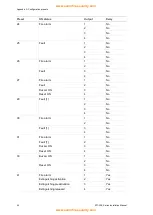
Страница 98: ...No 27 Fire alarm 1 No Fault 2 No Buzzer ON 3 No Reset ON 4 No 29 Fault 1 1 No 2 No 3 No 4 No 30 Fire alarm 1 No 2 No Fault 1 3 No 4 No 31 Fire alarm Fault 1 Buzzer ON Reset ON 1 No 2 No 3 No 4 No 33 Buzzer ON 1 No 2 No Reset ON 3 No 4 No 41 Fire alarm 1 Yes Extinguishing activation 2 Yes Extinguishing preactivation 3 Yes Extinguishing released 4 Yes www acornfiresecurity com www acornfiresecurity ...

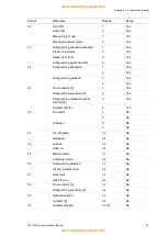
Страница 99: ...s 4 Yes 45 Fire sounders 2 1 Yes Extinguishing sounders 2 2 Yes Extinguishing released optical warning 2 3 Yes Actuator ON 2 4 Yes 46 Fire alarm 1 No 2 No Activated 3 No 4 No 47 Pre activated 1 2 No Released 3 4 No 48 Hold on 1 2 No Abort on 3 4 No 49 Manual mode 1 2 No Automatic mode 3 4 No 50 Extinguishing disabled 1 2 No Pressure switch fault 3 4 No 51 Door fault 1 2 No Gas Flow on 3 4 No 52 Fi...

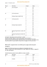
Страница 100: ...pansion board indications 3 Not considered to signal supervision faults and linked to the expansion I O indications 4 Faults are signaled in the Extinguishing Sounders LED Output activates continuously and the tone for activation or released has to be provided and configured in the sounder device EN 54 13 supervision and Class A expansion board outputs Note The following presets are available for ...

Страница 101: ...s Z2 and Z3 alarm 3 Yes 4 Yes 23 Z1 or Z2 alarm 1 Yes 2 Yes Z2 or Z3 alarm 3 Yes 4 Yes 24 Fire alarm 1 No 2 No 3 No 4 No 25 Fault 1 No 2 No 3 No 4 No 26 Fire alarm 1 No 2 No Fault 3 No 4 No 29 Fault 1 1 No 2 No 3 No 4 No 30 Fire alarm 1 No 2 No Fault 1 3 No 4 No 33 Buzzer ON 1 No 2 No Reset ON 3 No 4 No www acornfiresecurity com www acornfiresecurity com ...

Страница 102: ...n 3 4 No 49 Manual mode 1 2 No Automatic mode 3 4 No 50 Extinguishing disabled 1 2 No Pressure switch fault 3 4 No 51 Door fault 1 2 No Gas Flow on 3 4 No 52 Fire sounders 3 1 2 No Extinguishing sounders 3 3 4 No 53 Optical panel 3 1 2 No Actuator 3 3 4 No 55 Actuator blocked 1 2 3 4 No 80 Fire routing ON 1 No 2 No 3 No 4 No 90 Fire Sounders ON 1 No 2 No Extinguishing sounders ON 4 3 No 4 No 91 Fi...

Страница 103: ...ail safe mode output is active when there is no fault 2 Faults and disable options are linked to the expansion board indications 3 Not considered to signal supervision faults and linked to the expansion board indications 4 Faults are signaled in the Extinguishing Sounders LED Output activates continuously and the tone for activation or released has to be provided and configured in the sounder devi...

Страница 104: ...Appendix B Regulatory information Summary This section includes regulatory information for your control panel Content European standards 100 Declared performance 101 Electrical safety 101 www acornfiresecurity com www acornfiresecurity com ...

Страница 105: ...ype C only 8 3 Fault signals from points 8 4 Total loss of power supply 10 Test condition 1 Inputs and outputs on the optional 2010 1 SB expansion board do not support the optional requirement of EN 54 2 clause 7 8 and should not be used for fire alarm devices 2 Requires installation of optional 2010 1 SB expansion board not supplied Table 47 EN 12094 1 optional requirements Option Description 4 1...

Страница 106: ...cturing representative UTC Fire Security B V Kelvinstraat 7 6003 DH Weert The Netherlands Year of first CE marking 13 Declaration of Performance number 360 3117 2199 EN 54 EN 54 2 1997 AC 1999 A1 2006 EN 54 4 1997 AC 1999 A1 2002 A2 2006 EN 12094 1 2003 Product identification See model number on product identification label Intended use See DoP point 3 Essential characteristics See DoP point 9 Ele...

Страница 107: ...Appendix B Regulatory information 102 ZP1 X3E Series Installation Manual www acornfiresecurity com www acornfiresecurity com ...

Страница 108: ...d fault relays 20 auxiliary equipment 19 battery 18 disable extinguishing switch 12 expansion boards 20 extinguishing actuator output 16 extinguishing agent flow device 12 extinguishing MCP 11 fire detectors 9 fire MCP 9 fire network 20 inputs 10 low pressure indication switch 12 mains power supply 17 manual only mode control device 12 outputs 14 remote reset device 14 safety door fault monitoring...

Страница 109: ...31 O operating modes 2 output configuration presets 88 connections 14 functionality 14 termination 16 P password change 57 pressure switch type 43 product compatibility 2 R response times 73 S safety door fault delay 42 monitoring 42 seven segment display 28 T tone activation 44 released 44 U user interface BS 7273 26 standard 25 user levels 26 passwords and indications 27 Z zone configuration 7 5...

Отзывы: