Chapter 3: Configuration and commissioning
ZP1-X3E Series Installation Manual
45
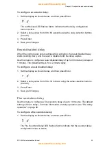
To configure the released tone:
1. Set the display as shown below, and then press Enter.
The red Extinguishing Sounders LED flashes fast to indicate that the
configuration menu is active.
2. Select a value using the value selection buttons (2 and 4).
3. Press Enter.
4. Save your changes.
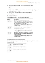
The available settings for this feature are shown below.
Display
Description
Pulsed mode
Continuous mode
Extinguishing zones
Use this menu option to define the extinguishing area required for your
installation.
The control panel provides three fire detection zones that can be assigned for
automatic detection of an extinguishing event. Fire detection zones that are not
linked to the extinguishing area are assigned standard fire detection functionality.
The configuration options available are shown in the table below.
Table 16: Extinguishing zone options
Option
Zones
Description
1
Z1
An alarm in Z1 initiates the extinguishing event. The control
panel provides standard fire detection for Z2 and Z3, both as
mixed zones.
2
Z1 and Z2 (default)
Both Z1 and Z2 must be in alarm to initiate an extinguishing
event. Z3 provides standard fire detection as a mixed zone.
3
Z1, Z2, and Z3
All three zones cover the extinguishing area. An alarm in any
two of the zones initiates an extinguishing event. None of the
zones provides standard fire detection functionality.
4
None
Only for fire. Extinguishing area is activated by an external
event for the network. Z1, Z2 and Z3 provide standard fire
detection as a mixed zone.
Note:
For connection information, see “Connecting zones with initiating devices ”
on page 7.


