Chapter 2: Installation
8
ZP1-X3E Series Installation Manual
Connecting zones
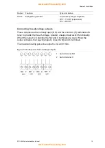
Figure 3 below shows connections for the default configuration (option 2).
Figure 3: Connecting zones for the default configuration
1. Zones in the extinguishing area
2. Zone for standard (mixed) fire detection
3. Galvanic barrier (for intrinsically safe
conventional detectors / intrinsically safe
mode only)
4. Zone termination (see “Terminating zones”
below)
Line resistance
Line resistance is shown in the following table.
Table 3: Zone line resistance values
Zone type
EN 54-2, BS 7273
EN 54-13
Intrinsically safe
Mixed detection
40 Ω max.
Not supported [1]
Not supported [1]
Automatic detection
55 Ω max.
50
Ω max
50
Ω max
Manual detection
55 Ω max.
50
Ω max
50
Ω max
[1] Mixed zones are not permitted in installations requiring EN 54-13 or intrinsically safe
configurations.
To measure the line resistance:
1. Disconnect all zone devices.
2. Create a short circuit at the end of the zone line.
3. Measure the resistance between the positive and negative lines with a
multimeter.
Terminating zones
Zone termination is required at all times, whether the zone is used or not. The
type of termination depends on the installation, as shown below.


