36
SECTION 7
GAS PURGE
This turbo molecular pump incorporates a gas purge port (Fig. 2-1 (2)). This turbo molecular
pump need to flow the purge gas for protection of the bearings, when it evacuates a lot of
corrosive gas. The proper purge gas flow rate is between 20 and 30 mL/min.
Joint
Orifice size
KF10
(
Dust cap
)
φ0.5
mm
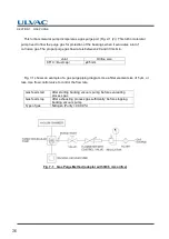
Fig. 7-1 shows an example of a gas purge piping diagram. Use a filter element size of 5
μ
m, or
less. Use flow control valve to control the flow rate.
Gas feed start
After starting backing vacuum pump; before evacuating
process gas
Gas feed stop
After
exhausting process gas sufficiently; before stopping
backing vacuum pump
Type of gas
Nitrogen (Purity > 99.99 %)
Fig. 7-1
Gas Purge Method (adaptor with
Φ0.5
mm orifice)
Содержание UTM-MS Series
Страница 2: ...No Text...
Страница 9: ...vii Introduction Location of Label...
Страница 12: ...x No Text...
Страница 16: ...xiv No Text...
Страница 17: ...1 1 Outline 1 2 Descriptions 1 2 1 Outside Drawing 1 2 2 Standard Accessories OUTLINE AND DESCRIPTIONS...
Страница 24: ...8 No Text...
Страница 25: ...2 1 Pump Main Unit IDENTIFICATION AND FUNCTION...
Страница 27: ...3 1 Pump Construction 3 2 Principle of Turbo Molecular Pumping CONSTRUCTION AND PRINCIPLE...
Страница 31: ...4 1 Standard Specifications for Pump Unit SPECIFICATIONS...
Страница 34: ...18 No Text...
Страница 50: ...34 No Text...
Страница 51: ...GAS PURGE...
Страница 58: ...42 No Text...
Страница 59: ...9 1 Vacuum Pressure Rise 9 2 Abnormal Noise and or Vibration TROUBLESHOOTING...


