


https://ucore-electronics.com
52
10.3.1.
Creating a database
In the
“
Advanced Mode
”
tab, the
“
Enable Database Mode
”
checkbox is checked to activate the database
mode. The first thing to do when creating a database is to load the electronic board image. To do this, click
the
“
Load Image
”
button. On the page that opens (Figure 20), the image of the electronic board to be
recorded is loaded by clicking the
“
Load
” button.
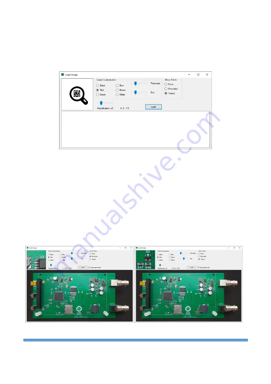
Figure 20. Overview of the Load Image window
On this window, cursor customization can be done. Depending on the color and density of the PCB, the
color, size and thickness of the cursor can be changed by the user. There is also a magnifying screen. The
position of the cursor on the PCB is seen more clearly in this area (Figure 21).
There are 3 features in the
Show Points
section.
•
None
: does not show any data on the image.
•
Recorded
: Shows all recorded points on the image.
•
Tested
: Marks the points according to the result of the test during the auto-test. The points that
pass the test are marked in green, and those that fail the test are marked in red.
Figure 21. Load Image window (display of recorded and tested points)


