


https://ucore-electronics.com
49
Dual Mode:
It allows simultaneous use of Probe-1 (yellow color) and Probe-2 (red color) channels. If a
single channel is used, only Probe-1 is active.
Compare:
Compares the similarity between two channels. DUAL mode must be active for comparison.
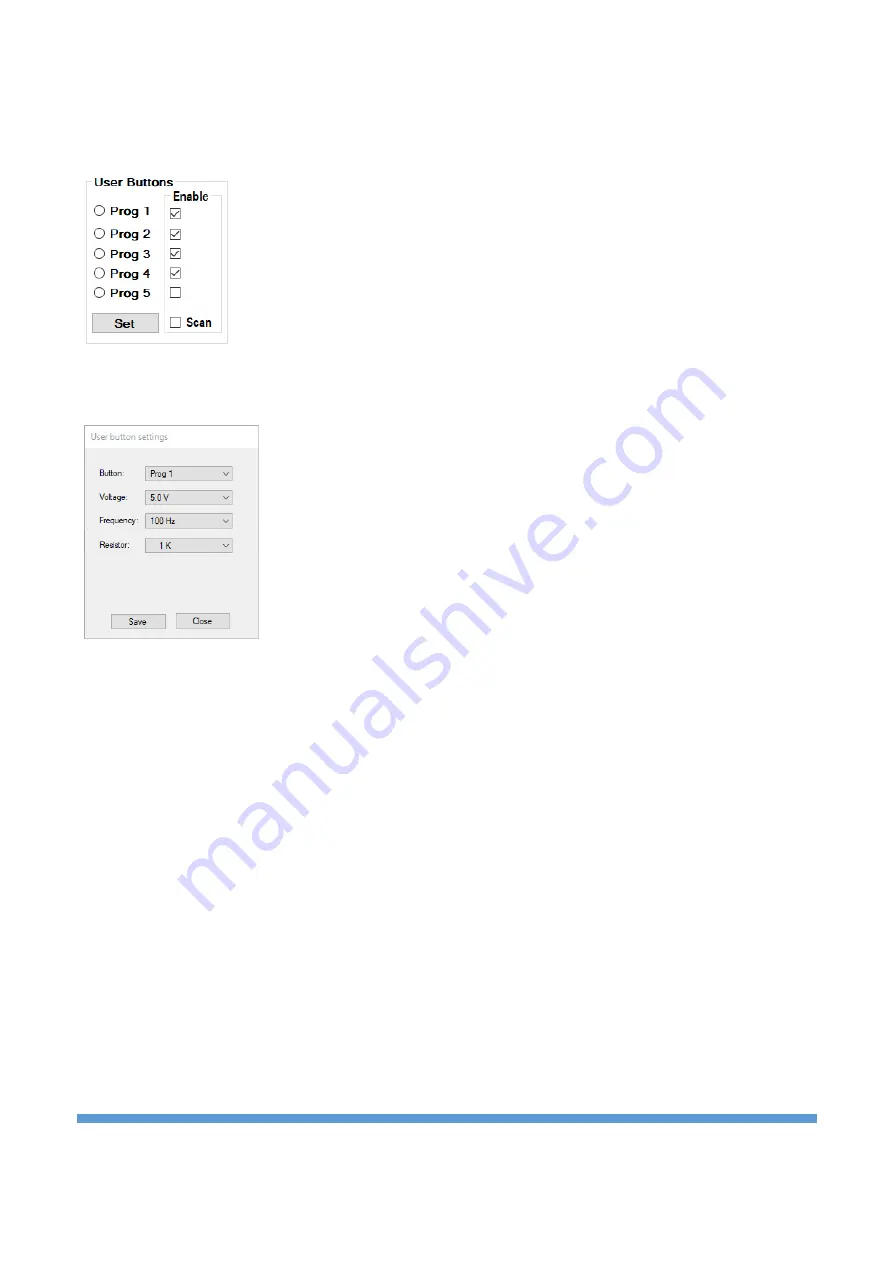
Prog 1-5
: There are 5 programmable user buttons. Selected voltage, frequency and
limit resistor combinations are stored in the memory.
Scan:
Scans user buttons at regular intervals. By removing the tick next to the stage
that is undesirable to be scanned, it is canceled.
Set:
Programs user buttons. Clicking the button opens a new window. Voltage, frequency, resistance
combinations are created in the window that opens. Then the button to be saved at the top is selected and
the settings are saved by clicking th
e “
Save
” button. Click the “
Close
”
button to close the window.
Save As:
When this button is clicked, the impedance graph is saved to the computer in picture format
(bmp, jpg, png, gif) (Figure 17).
Advanced Mode:
It is the menu where operations related to the database are made (Figure 18).
Comparison tests are performed within a certain tolerance and this variable can be set by the user in this
menu in percent. The result of the comparison is reported visually and audibly by the program. If the
audible warning is not preferred, this feature can be turned off by the user from this menu.
In this menu, a database can be created for different electronic boards. The impedance curve of each point
on the PCB is recorded. These records are matched with the visual image of the PCB to see which
impedance curve is at which coordinate when testing the same board in the future. Thus, a very fast test is
provided.
In order to use this feature, this mode must be activated first. When
“
Enable Database Mode
”
is checked,
“
Database Mode
”
is accessed.


