


https://ucore-electronics.com
36
9.2.
System info
It is the section that shows some analog data read on the motherboard. It contains information about
system voltages and internal battery.
9.3.
LCD Back Light
The backlight of the LCD can be adjusted here. By clicking the “
+
” and “
-
” buttons, the backlight intensity is
adjusted between 25% and 100%. In addition, it can be changed by rotating the Rotary-3.
When the “
EXIT
”
button is clicked, the data is saved.
Note:
If the battery charge drops below 20% while the device is running on battery, the backlight is
automatically dimmed to reduce energy consumption. If the battery voltage drops below the
critical level (< 3.0V), the backlight is completely turned off and the device stops working. In terms
of battery health, the battery should be recharged as soon as possible.
9.4.
Calibration & Settings
Here, calibration and some settings related to the device are made. Factors such as heat, dust and humidity
reduce the performance of the device over time. In such cases, calibration can increase the performance of
the device.
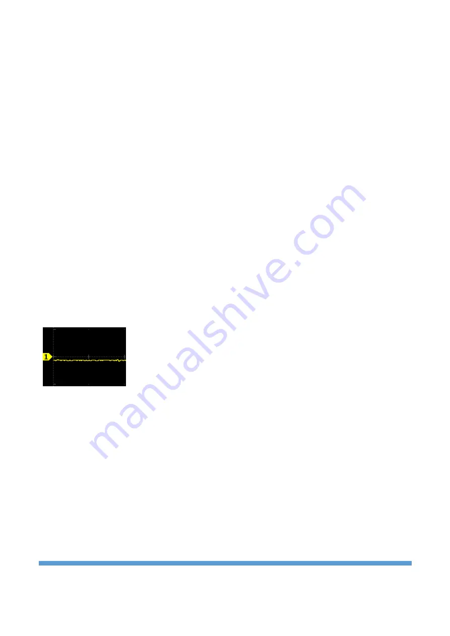
DSO OFFSET calibration:
When there is no signal at the input in the oscilloscope mode (or when the probe tips are short-circuited), if
the signal is not at zero volts, then an offset calibration should be performed.
Offset shift in negative direction in CH-1
For this, the “
DSO OFFSET
” bu
tton is clicked. In the calibration submenu at the top, text appears stating
that no signal should be applied to the input. If probes are attached to the oscilloscope inputs (CH-1 and
CH-2) while performing the offset calibration, the probes must also be removed. Then click on the
“
Calibrate
”
button in the submenu. At the end of this process, an information message that the calibration
is finished appears in the information window next to the button.


