45
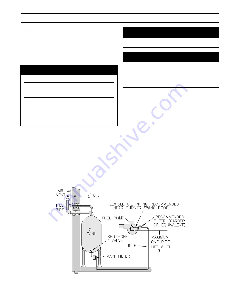
Figure 29: Single Pipe Oil Line
VIII. OIL PIPING
A.
GENERAL
1. Use flexible oil line(s) so the burner swing door can be
opened without disconnecting the oil supply piping.
2. A supply line fuel oil filter is recommended as a minimum
for all firing rates but a pleated paper fuel oil filter is
recommended for the firing rates below 1.0 GPH to
prevent nozzle fouling.
NOTICE
Do not use compression fittings.
Oil piping must be absolutely airtight or leaks or
loss of prime may result. Bleed line and fuel unit
completely.
Refer to your local jurisdictions regarding
any special considerations for fuel supply
requirements. In addition, refer to NFPA 31,
Standard for the Installation of Oil-Burning
Equipment for Installations in the United States
and CSA B139-04 for Installation in Canada.
3. Use of a high efficiency micron filter (Garber or
equivalent) in addition to a conventional filter is highly
recommended.
4. Piping used to connect the oil burner to the oil supply
tank shall not be smaller than 3/8" iron pipe or 3/8" OD
copper tubing. Copper tubing shall have a .032" minimum
wall thickness.
WARNING
Under no circumstances can copper with sweat
style connectors be used.
NOTICE
Some jurisdictions require the use of a fusible
shutoff valve at the tank and/or the burner. In
addition, some jurisdictions require the use of a
fusible electrical interlock with the burner circuit.
Check your local Codes for special requirements.
B.
SINGLE PIPE OIL LINES
1. Standard burners are provided with single-stage 3450 RPM
fuel units with the bypass plug removed for single-pipe
installations.
2. The single-stage fuel unit may be installed single-pipe
with gravity feed or lift. Maximum allowable lift is 8
feet. See Figure 29.
3. Fuel Oil Line Deaerator – On many occasions a leaky
oil delivery line can introduce air into the fuel oil supply
system. This often creates a rough starting condition and
can create a burner lockout state. In addition to fixing the
leak, a fuel line deaerator can be installed to eliminate
air. The single line from the fuel tank is connected to
the deaerator. The burner pump must be connected to
the deaerator as a two pipe system. Follow the oil pump
manufacturer’s recommendations for conversion to a two
pipe system.
Содержание MPO - IQ
Страница 6: ...6 Figure 1 MPO IQ84 Thru MPO IQ231 Water Boiler ...
Страница 22: ...22 Figure 11 Boiler Removal from Skid III UNIT PAK BOILER ASSEMBLY TRIM CONTROLS continued ...
Страница 27: ...27 Figure 13A Recommended Water Piping for Circulator Zoned Heating Systems IV WATER Boiler PIPING continued ...
Страница 28: ...28 Figure 13B Recommended Water Piping for Zone Valve Zoned Heating Systems IV WATER Boiler PIPING continued ...
Страница 42: ...42 Figure 28A Schematic Wiring Diagram VII ELECTRICAL continued ...
Страница 43: ...43 Figure 28B Schematic Wiring Diagram Burner Options VII ELECTRICAL continued ...
Страница 44: ...44 Figure 28C Ladder Diagram VII ELECTRICAL continued ...
Страница 70: ...70 Bare Boiler Assembly XIV Repair Parts continued ...
Страница 72: ...72 Jacket Assembly XIV Repair Parts continued ...
Страница 74: ...74 MPO IQ84 Thru MPO IQ231 Water Boilers Trim and Controls XIV Repair Parts continued ...
Страница 78: ...78 Beckett AFG Burner XIV Repair Parts continued ...
Страница 80: ...80 Beckett NX Burner XIV Repair Parts continued ...
Страница 92: ...92 U S Boiler Company Inc P O Box 3020 Lancaster PA 17604 1 888 432 8887 www usboiler net ...


