3. SPECIFICATIONS
Description
T233HST/T273HST
Radiator core type
Flat water tube with corrugate fins
Core train number
4 trains
Radiator fin pitch
3.8 mm
Thermal radiator area
7.1362
㎡
㎡
㎡
㎡
Pressure valve opening pressure
0.9
±
0.15Kgf/
㎠
Coolant capacity
5.2
ℓ
(contains in cylinder block), Radiator : 2.38
ℓ
Test pressure
1.5Kgf/
㎠
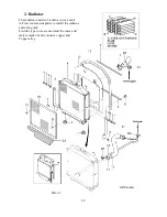
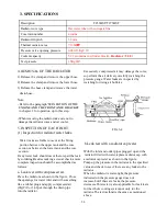
4. REMOVAL OF THE RADIATOR
1) Release the clamp and remove the upper hose.
2) Release the clamp and remove the lower hose.
3) Release the hose clamp and remove the water
drain hose.
Note:
- Refer to the paragraph”SEPARATION OF THE
ENGINE AND THE FRONT AXLE BRACKET
Excessively compressed air may damage the cores,
so perform the air delivery carefully,watching the
pressure gauge. Water leaks are inspected by
watching for rising air bubbles.
ENGINE AND THE FRONT AXLE BRACKET
in chapter 2 for operation up to this step.
-When removing the radiator,take care not to
damage the radiator cores and oil cooler.
5. INSPECTION OF EACH PART
(1) Inspection for radiator water leaks.
Water leaks are liable to occur at the fitting
portion between the upper tank and the core
section or between the lower tank and the core
section.
If any water leak should occur there,repair the leak
by soldering.Besides making a visual check,a more
complete inspection should be accomplished as
follows:
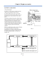
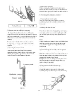
a. Leak test with compressed air.
Place the radiator as shown in the figure. Close
the openings for water inlet and with something
like a rubber plug and apply compressed air
(1
㎏
f/
㎠
or 14.2psi) through the drain pipe
into the radiator.
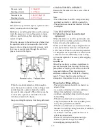
b.Leak test with a radiator cap tester
With the inlet and outlet pipes plugged up and the
radiator filled with water,replace radiator cap with
a radiator cap tester as shown in the figure.
Pump up the pressure in the radiator to the specified
value and check to see if there are any leaks in the
radiator.
When the radiator is water-tight,the pressure
indicated on the pressure gauge does not
increase,but if there are leaks,the pressure
decreases.This tester is also applicable for leak tests
for the whole cooling system,not only for the
radiator.The test method is the same as mentioned
above.
FIG.3-4
3-3
Содержание T233 HST
Страница 14: ...1 11...
Страница 15: ...1 12...
Страница 22: ...SECTION 3 GEAR TRAIN DIAGRAMS FIG 1 3 GEAR TRAIN DIAGRAM 1 19...
Страница 33: ...SECTION 2 OPERATION CHART FOR DISASSEMBLY AND REASSEMBLY BY MAJOR BLOCKS 2 4...
Страница 60: ...3 HST main pump case 4 5...
Страница 64: ...6 Hydrostatic system schematic 4 8...
Страница 100: ...3 Rear transmission case 5 15 Fig 5 23...
Страница 121: ...Power Train Diagram Fig 5 60 5 36...
Страница 210: ...SECTION 6 WIRING DIAGRAM 10 12...


