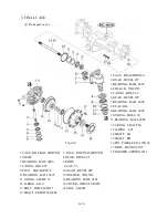
1.1.DISASSEMBLY
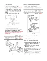
1) Dismount the front wheel drive shaft,
referring to the pertinent paragraph in
chapter 2.
2) Remove the right and left tie rods.
3) Suspend the front axle bracket with a chain.
4) Remove the front metal clamping bolts. The
front axle can then be separated from the axle
bracket.
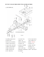
5) Remove the front and rear pivot metals.
1.2.INSPECTION
1) FRONT AXLE SHAFT DIAMETER
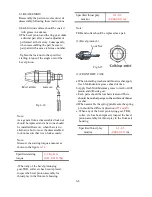
Measure the diameter at a roll bush contact point
with a micro-meter or vernier calipers.If the
2) FRONT AXLE BUSH BORE DIAMETER
Measure the bore diameter of the roll
bush in the pivot metal(F). If the measured value
exceeds the usable limit, replace the bush.
Front
rear
Standard value as assembled
Ø50
Ø60
Usable limit
Ø50.35
Ø60.35
Fig.6-4
with a micro-meter or vernier calipers.If the
measured value is less than usable limit,
replace the
housing front axle or bush in Metal pivot (F)or
Metal pivot (R) .
Front
rear
Standard value as assembled
Ø50
Ø60
Usable limit
Ø49.9
Ø59.9
3) Worn or damaged oil seals, O-rings,
bearings, etc. should be replaced.
1.3 REASSEMBLY
Reassemble the parts in reverse order of
disassembly, following these instructions.
1) Lips of the oil seals, bush contact surfaces,
and O-rings should be coated with grease
in advance.
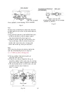
2) When installing the roll bushes, abide by
the following precautions.
-Use an installer and press in the bush on a press.
-The bore surface should be coated with grease
in advance.
-The shim of the roll bush should reach position
as shown Fig.6-7. In other words the seam
should be in a position which is free from any
load.
Fig.6-5
Fig.6-6
6-4
Содержание T233 HST
Страница 14: ...1 11...
Страница 15: ...1 12...
Страница 22: ...SECTION 3 GEAR TRAIN DIAGRAMS FIG 1 3 GEAR TRAIN DIAGRAM 1 19...
Страница 33: ...SECTION 2 OPERATION CHART FOR DISASSEMBLY AND REASSEMBLY BY MAJOR BLOCKS 2 4...
Страница 60: ...3 HST main pump case 4 5...
Страница 64: ...6 Hydrostatic system schematic 4 8...
Страница 100: ...3 Rear transmission case 5 15 Fig 5 23...
Страница 121: ...Power Train Diagram Fig 5 60 5 36...
Страница 210: ...SECTION 6 WIRING DIAGRAM 10 12...


