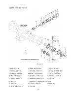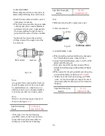
6) Drive pinion Sub assembly
1.C-RING , SHAFT
2.GEAR , SPUR 21T
3.BOLT , HEX/S
4.METAL , PINION
5.PIN , PARALLEL/A
6.METAL , BEARING
7.SHIM , 0.1
8.SHIM , 0.2
9.BEARING, TAPER
ROLLER(30304J)
10.GEAR , SPUR 17-27T
11.C-RING , SHAFT
12.GEAR , SPUR 17T
13.BEARING , BALL(6306)
14.BEARING , BALL/HL1(6306)
15.FORK , RANGE
16.STAY , RANGE
17.SPRING , SHIFTER
18.BALL , STEEL 5/16
19.BEARING , BALL/HL1 (6206)
20.GEAR , SPUR 19-28T
21.BEARING , NEEDLE.
Note:
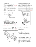
a.Apply oil to the drive pinion and related parts ahead of time. Then install them and tighten the
assembly to the specified torque.
b.Be sure that the starting torque of the drive pinion meets the specified level.
Starting torque is 8-11 Kgf.m (0.08-0.11KN.cm) and c
an be checked by a special jig.
c.After the starting torque has been adjusted to the specified level, crimp the bolts at metal as illustrated.
d. Be sure that these parts should turn smoothly
When the drive pinion or the ring gear has been replaced, the proper number of shims to be installed
should be determined based upon the following procedure:
Fig.5-57
5-31
Fig.5-52
21.BEARING , NEEDLE.
ROLLER (KT252913)
22.GEAR , SPUR 28T
23.WASHER , 20X34X3
24.BEARING , BALL/HL1(6304)
25.Pinion shaft
Содержание T233 HST
Страница 14: ...1 11...
Страница 15: ...1 12...
Страница 22: ...SECTION 3 GEAR TRAIN DIAGRAMS FIG 1 3 GEAR TRAIN DIAGRAM 1 19...
Страница 33: ...SECTION 2 OPERATION CHART FOR DISASSEMBLY AND REASSEMBLY BY MAJOR BLOCKS 2 4...
Страница 60: ...3 HST main pump case 4 5...
Страница 64: ...6 Hydrostatic system schematic 4 8...
Страница 100: ...3 Rear transmission case 5 15 Fig 5 23...
Страница 121: ...Power Train Diagram Fig 5 60 5 36...
Страница 210: ...SECTION 6 WIRING DIAGRAM 10 12...


