0
1
2
3
4
5
6
7
8
9
DRAWN BY
MACHINE TYPE :
DIAGRAM VERSION
DATE
NEXT PAGE
PAGE
TOTAL PAGES
10
1
1
Gustavo Morejon
1
00
01
02
03
04
05
06
07
08
0
9
10
11
00
01
02
03
04
05
06
07
0CH
100CH
1
2
3
4
5
6
7
8
9
10
11
12
13
14
1
2
3
4
5
6
out
sens.
1
2
3
4
5
6
7
8
9
10
11
12
13
14
S1
Slide sensor
com
no
S2
Limit Switch
com
no
S3
com
no
First Part
S4
G-Stop
com
no
S6
Transfer Tip
com
no
S5
On/Off
Sensor
com
no
Transfer Arm Cyl
Slide Cyl
Crimp Cyl
Prox Sen.
CN1F
CN1M
+
_
24VDC
0VDC
24VDC
POWER
SUPPLY
7
8
9
10
11
12
17
13
14
15
7
8
9
10
11
12
13
14
15
0
1
L
N
G
110VAC
CP1L-
L20D
T-D
CRIMPER
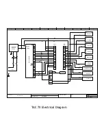
TAC 7X Electrical Diagram
Содержание TAC-7AE
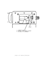
Страница 6: ...Figure 1 1 TAC 7X Front View ...
Страница 8: ... Figure 1 2 Wire Insertion Through Funnel ...
Страница 12: ...Figure2 1 Pneumatic Hook Up ...
Страница 14: ... Fiqure 2 4 Track Drop Tube Escapement ESCAPEMENT SYSTEM _ _ _ BR ASSEMBL I TRA ...
Страница 18: ... ARBOR COVER PLA TE REMOVED Figure 3 1 Crimp Cylinder Arbor Open ...
Страница 20: ... ARBOR COVER PLAT E REMOVED Figure 3 2 Crimp Cylinder Arbor Closed ...
Страница 23: ... Crimp Inspection Points Improper Crimps ...
Страница 33: ...Figure 6 1 TAC 7X Components ...
Страница 34: ...Figure 6 2 Control Box Components Figure 6 2 TAC 7X Components Right View ...
Страница 35: ...PLC Controller Switching Power Supply Vibratory Feed Controller Figure 6 3 TAC 7X Components Left View ...
Страница 37: ...Figure 6 3 Contact Track Feed Air Adjustments ...
Страница 42: ... Figure 6 4 Indenter Plate Removal ...
Страница 43: ...HOSE CLAMP CAREFULL Y REMOVE Figure 6 5 Indenter Replacement ...
Страница 47: ...Figure 6 6 Indenter Adjustment ...
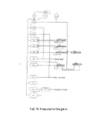
Страница 52: ...TAC 7X Pneumatic Diagram ...

