TAC-7X
MANUAL
•
Verify that a contact is present and fully seated in the
transfer tip. S-6 must be switched on for crimp activation to
occur. (This is a safety feature of TAC operation).
- Verify that the "O" Ring has not fallen out of the N-1
Sensor Bracket
•
Verify performance of slide sensor switch S-1 by
performing the following:
Step 1.
Step 2.
Step 3.
Step 4.
Step 5.
Step 6.
Step 7.
Turn air supply off
*Remove Transfer Tip*
Remove power cord from outlet
Remove control unit cover
Turn air on
Locate S-1 and slide sensor line
Fully pinch slide sensor line repeatedly and verify if
S-1 is switching on and off. An audible click should
be heard from switch each time it is activated.
NOTE
8.
lndenters
Replacement
Should the work environment be too noisy for an
effective audible check, an electrical meter may be
used instead. (Top tab is common, middle tab is
normally open position).
Step 8.
lf switch S-1fails the above test, consult factory
for adjustment instructions. No adjustments
should be attempted prior to factory instructions.
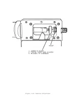
lndenters are adjustable and replaceable. The procedure described herein
is for the physical replacement of the indenters. The adjustment procedure
for both new and already installed indenters is given in paragraph 6-9.
·
-
Upon completion of the installation and adjustment of new indenters,
perform a crimp verification (Section 3).
Содержание TAC-7AE
Страница 6: ...Figure 1 1 TAC 7X Front View ...
Страница 8: ... Figure 1 2 Wire Insertion Through Funnel ...
Страница 12: ...Figure2 1 Pneumatic Hook Up ...
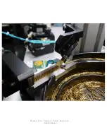
Страница 14: ... Fiqure 2 4 Track Drop Tube Escapement ESCAPEMENT SYSTEM _ _ _ BR ASSEMBL I TRA ...
Страница 18: ... ARBOR COVER PLA TE REMOVED Figure 3 1 Crimp Cylinder Arbor Open ...
Страница 20: ... ARBOR COVER PLAT E REMOVED Figure 3 2 Crimp Cylinder Arbor Closed ...
Страница 23: ... Crimp Inspection Points Improper Crimps ...
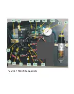
Страница 33: ...Figure 6 1 TAC 7X Components ...
Страница 34: ...Figure 6 2 Control Box Components Figure 6 2 TAC 7X Components Right View ...
Страница 35: ...PLC Controller Switching Power Supply Vibratory Feed Controller Figure 6 3 TAC 7X Components Left View ...
Страница 37: ...Figure 6 3 Contact Track Feed Air Adjustments ...
Страница 42: ... Figure 6 4 Indenter Plate Removal ...
Страница 43: ...HOSE CLAMP CAREFULL Y REMOVE Figure 6 5 Indenter Replacement ...
Страница 47: ...Figure 6 6 Indenter Adjustment ...
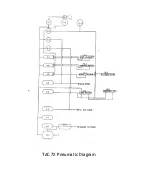
Страница 52: ...TAC 7X Pneumatic Diagram ...

