TAC-7X
MANUAL
Maintenance
&
Troubleshoot ing
Section 6
1.
Introduction
2.
Preventative
Maintenance
NOTE
The primary purpose of the Maintenance and Troubleshooting section of
this manual is to permit the user to perform required preventive
maintenance, perform minor adjustments and to correct minor malfunc-
tions caused by incorrect/unacceptable contacts.
Detailed instructions for adjusting and changing indenters are also given.
In the event it is necessary to replace an item which has become defective
and for which there is no specific disassembly instructions, use extreme
care and/or consult the factory for assistance.
The only preventive maintenance required for the TAC is the periodic
inspection and replacement of air filter F-1 and vacuum filter RFV-1. See
Figure 6-2. Whenever it is observed that filter F1 has accumulated
moisture on the bottom, the moisture should be drained by placing a cup or
other container under F1, opening the sleeve valve, opening the F1 drain,
and draining the filter.
Do not allow the moisture to spray, drip or enter the
cabinet when draining.
The vacuum filter RFV-1 can easily be located in-line between the transfer
tip holder and the TAC Control Unit. If the vacuum filter becomes clogged,
decreased performance with part detection at the transfer tip will be
observed. When this situation occurs, replacement of the vacuum filter is
suggested. Please note the vacuum filter orientation when removing, as
the replacement filter must be installed with the same orientation.
A vacuum circuit purge is also suggested any time a degraded perfor-
mance of part detection occurs. This can be done by performing the
following steps: (Refer to Figure 6-1and 6-2).
Step 1. Turn off air supply.
Step 2. Unplug Power cord from wall outlet.
Step 3. Remove the transfer tip from the tip holder.
Step 4. Remove control unit cover plate.
Содержание TAC-7AE
Страница 6: ...Figure 1 1 TAC 7X Front View ...
Страница 8: ... Figure 1 2 Wire Insertion Through Funnel ...
Страница 12: ...Figure2 1 Pneumatic Hook Up ...
Страница 14: ... Fiqure 2 4 Track Drop Tube Escapement ESCAPEMENT SYSTEM _ _ _ BR ASSEMBL I TRA ...
Страница 18: ... ARBOR COVER PLA TE REMOVED Figure 3 1 Crimp Cylinder Arbor Open ...
Страница 20: ... ARBOR COVER PLAT E REMOVED Figure 3 2 Crimp Cylinder Arbor Closed ...
Страница 23: ... Crimp Inspection Points Improper Crimps ...
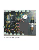
Страница 33: ...Figure 6 1 TAC 7X Components ...
Страница 34: ...Figure 6 2 Control Box Components Figure 6 2 TAC 7X Components Right View ...
Страница 35: ...PLC Controller Switching Power Supply Vibratory Feed Controller Figure 6 3 TAC 7X Components Left View ...
Страница 37: ...Figure 6 3 Contact Track Feed Air Adjustments ...
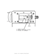
Страница 42: ... Figure 6 4 Indenter Plate Removal ...
Страница 43: ...HOSE CLAMP CAREFULL Y REMOVE Figure 6 5 Indenter Replacement ...
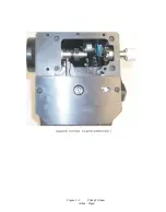
Страница 47: ...Figure 6 6 Indenter Adjustment ...
Страница 52: ...TAC 7X Pneumatic Diagram ...

