TAC-7X
MANUAL
Step 2. Verify the alignment between the transfer tip and drop tube. If
alignment appears off, consult the factory or your local area
service representative for further instructions.
Step 3. If contact is fully seated in proper transfer tip, verify transfer tip
sensor S-6 is operational by performing the following:
A - Turn air off.
B - Remove contact from transfer tip.
C - Remove Power Cord from wall outlet.
D - Remove control unit cover.
E - Turn air on.
F - Locate S-6 and vacuum line.
G - Fully pinch vacuum line repeatedly and verify if S-6 is
switching on and off. An audible click should be heard from
the switch each time it is activated.
NOTE
Should the work environment be too noisy for an
effective audible check, an electrical meter may be
used instead. (Top tab is common, bottom tab is
normally open position).
Step 4.
If switch S-6 fails the above test, consult factory for adjustment
instructions. No adjustments should be attempted prior to
factory instructions.
7.
Trigger (Slide
Sensor)
Inserting a conductor into a contact and depressing it forces the transfer tip
slide down onto a slide sensor, initiating the crimp cycle.
If depressing the conductor into a contact does not initiate the crimp cycle,
perform the following checks:
-
With air turned off, inspect the trigger assembly to be sure
no foreign objects have lodged themselves in any of the
moving parts.
Содержание TAC-7AE
Страница 6: ...Figure 1 1 TAC 7X Front View ...
Страница 8: ... Figure 1 2 Wire Insertion Through Funnel ...
Страница 12: ...Figure2 1 Pneumatic Hook Up ...
Страница 14: ... Fiqure 2 4 Track Drop Tube Escapement ESCAPEMENT SYSTEM _ _ _ BR ASSEMBL I TRA ...
Страница 18: ... ARBOR COVER PLA TE REMOVED Figure 3 1 Crimp Cylinder Arbor Open ...
Страница 20: ... ARBOR COVER PLAT E REMOVED Figure 3 2 Crimp Cylinder Arbor Closed ...
Страница 23: ... Crimp Inspection Points Improper Crimps ...
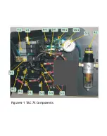
Страница 33: ...Figure 6 1 TAC 7X Components ...
Страница 34: ...Figure 6 2 Control Box Components Figure 6 2 TAC 7X Components Right View ...
Страница 35: ...PLC Controller Switching Power Supply Vibratory Feed Controller Figure 6 3 TAC 7X Components Left View ...
Страница 37: ...Figure 6 3 Contact Track Feed Air Adjustments ...
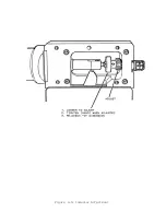
Страница 42: ... Figure 6 4 Indenter Plate Removal ...
Страница 43: ...HOSE CLAMP CAREFULL Y REMOVE Figure 6 5 Indenter Replacement ...
Страница 47: ...Figure 6 6 Indenter Adjustment ...
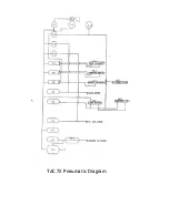
Страница 52: ...TAC 7X Pneumatic Diagram ...

