TAC-7X
MANUAL
2-3-1 Electrical
Installation
4. Initial
Checkout
CAUTION
5. Tool
Sets
Connect the TAC power cord to a grounded 11SVAC,60 Hz, SA power
source. (European 220 VAC, SO Hz, SA).
Perform the following to ensure that the feeder-bowl is functioning properly
and that air pressure is adequate.
If any observation is not as specified, refer to (Section 6). Maintenance
and Troubleshooting, before proceeding.
Step 1.
Turn the air supply ON by moving the sleeve valve forward.
Step 2.
Check the air gauge to ensure a pressure of about 80 PSI at
G-1.
Step 3.
Turn ON the FEEDER-BOWL ON/OFF switch.
Step 4.
While gently touching the feeder-bowl with your right hand,
slowly rotate the FEEDER-BOWL SPEED CONTROL .
Step 5.
Note that the feeder-bowl vibrates more rapidly when the
SPEED control is rotated clockwise and vibrates less rapidly
when the SPEED control is rotated counterclockwise.
Step 6.
Close the sleeve valve to turn the air supply and power to the
controller OFF.
Each contact requires its own unique tool set. This set includes transfer tip,
track assembly and escapement spacer. These exactly machined parts are
already installed and configured per your requirements.
Содержание TAC-7AE
Страница 6: ...Figure 1 1 TAC 7X Front View ...
Страница 8: ... Figure 1 2 Wire Insertion Through Funnel ...
Страница 12: ...Figure2 1 Pneumatic Hook Up ...
Страница 14: ... Fiqure 2 4 Track Drop Tube Escapement ESCAPEMENT SYSTEM _ _ _ BR ASSEMBL I TRA ...
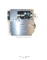
Страница 18: ... ARBOR COVER PLA TE REMOVED Figure 3 1 Crimp Cylinder Arbor Open ...
Страница 20: ... ARBOR COVER PLAT E REMOVED Figure 3 2 Crimp Cylinder Arbor Closed ...
Страница 23: ... Crimp Inspection Points Improper Crimps ...
Страница 33: ...Figure 6 1 TAC 7X Components ...
Страница 34: ...Figure 6 2 Control Box Components Figure 6 2 TAC 7X Components Right View ...
Страница 35: ...PLC Controller Switching Power Supply Vibratory Feed Controller Figure 6 3 TAC 7X Components Left View ...
Страница 37: ...Figure 6 3 Contact Track Feed Air Adjustments ...
Страница 42: ... Figure 6 4 Indenter Plate Removal ...
Страница 43: ...HOSE CLAMP CAREFULL Y REMOVE Figure 6 5 Indenter Replacement ...
Страница 47: ...Figure 6 6 Indenter Adjustment ...
Страница 52: ...TAC 7X Pneumatic Diagram ...


