background image

AI1422E Reader

TransCore Proprietary

8-5

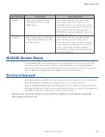
AI1422E Reader Repair

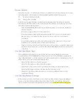
The AI1422E Reader is designed for whole-unit replacement and is manufactured with 
surface-mounted components. It requires sophisticated testing and repair equipment. 
All testing and repairs are performed at TransCore’s factory. Please contact TransCore to 
obtain a Return Materials Authorization (RMA) for returning the reader.

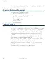
Technical Support

Authorized dealers and distributors are responsible for the direct support of all customers. 
Authorized dealers and distributors needing support can contact Technical
Support at (505) 856-8007. Please be prepared to answer a series of questions that are 
designed to direct you to the best TransCore support resource available. These questions 
will relate to symptoms, configuration, model, and tags used.

Note: End users and facility operators contacting Technical Support will be referred to the dealer 
responsible for the system sale.

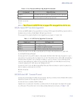
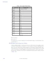
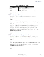
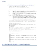
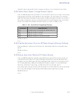
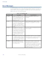
Error Message

Description

Corrective Action

ErrorRF2

Warning message that the RF 
module did not return an INIT 
DONE signal

If the reader indicates a single ErrorRF2 
event and recovers from the error, no 
corrective action is required. You may want 
to track this error message if it should occur 
again. If the reader indicates repeated 
ErrorRF2 warning messages then return the 
reader to the factory.

ErrorRF3

Warning message of unexpected 
status read, including status byte, 
from RF module

If the reader indicates a single ErrorRF3 
event and recovers from the error, no 
corrective action is required. You may want 
to track this error message if it should occur 
again. If the reader indicates repeated 
ErrorRF3 warning messages then return the 
reader to the factory.

Содержание 1422E

Страница 1: ...This guide provides on site test procedures useful in troubleshooting any problems encountered after installation Command codes which allow the user to configure the reader system for communicating w...

Страница 2: ...tered trademarks and are used under license All other trademarks are the property of theirrespective owners Contents are subject to change Printed in theU S A For further information contact TransCore...

Страница 3: ...15 of the FCC rules These limits are designed to provide reasonable protection against harmful interference when the equipment is operated in a commercial environment This equipment generates uses an...

Страница 4: ...A en accord avec la partie 15 des directives de la FCC Ces normes visent assurer une protection raisonnable contre les interf rences nuisibles lorsque l appareil est utilis dans un environnement comme...

Страница 5: ...operation of the device AVERTISSEMENT AUX UTILISATEURS AU CANADA INDUSTRIE CANADA IC INDUSTRIE CANADA RADIO STANDARD SPECIFICATIONS CNR 137 EMPLACEMENT ET SERVICE DE SURVEILLANCE DANS LA BANDE 902 928...

Страница 6: ...in that this equipment is certified for use in a final installation the minimum safe distance was calculated to be 8in 20cm FCC Federal Communication Commission FCC an agency of The United States of A...

Страница 7: ...ntrolled Environment Power density 0 6455 frequency in MHz 0 5 W m2 with a Reference Period time of 6 Min General Public Uncontrolled Environment Power density 0 02619 frequency in MHz 0 6834 W m2 wit...

Страница 8: ...s certified for the recommendation for each of the operation environments is as follows 1 The antenna should be installed at least 47in 120cm from the General Population Public i e Uncontrolled Enviro...

Страница 9: ...re soit 6 minutes En utilisant la fr quence de 915 MHz milieu de la bande de fr quences de cet appareil et le gain d antenne maximal pour lequel cet appareil a re u une certification d utilisation dan...

Страница 10: ...n utilisant la fr quence de 915 MHz milieu de la bande de fr quences de cet appareil et le gain d antenne maximal pour lequel cet appareil a re u une certification d utilisation dans une installation...

Страница 11: ...ertification les recommandations pour chaque environnement d exploitation sont les suivantes 1 L antenne devrait tre install e au moins 120 cm 47 po de la population g n rale du grand public c est dir...

Страница 12: ...3 2 Antenna Interface 3 2 Interface Selection Switch 3 2 Main RS 232 Interface 3 2 Aux RS 232 Interface 3 3 RS 422 Interface 3 3 Ethernet M12 Interface 3 3 Customer I O Interface 3 4 Installation Ins...

Страница 13: ...mmand Group 2 7 6 Append Information Command Group 3 7 7 ID Filtering Command Group 4 7 9 Reader Status Command Group 5 7 15 Reader Control Functions Command Group 6 7 25 Auxiliary Reader Control Comm...

Страница 14: ...Tag Centerline Tolerance 2 5 Figure 3 1 Sample Front Panel of an AI1422E Reader 3 2 Figure 3 2 RS 232 DE09 Inerface Connector Pin outs 3 3 Figure 3 3 Customer I O Interface Pin outs 3 4 Figure 5 1 Pow...

Страница 15: ...Status 7 19 Table 7 9 Open Closed Conditions for Output Status IAG Applications 7 19 Table 7 10 Open Closed Conditions for Input Status 7 19 Table 7 11 Output Control Commands 7 27 Table 7 12 RF Contr...

Страница 16: ...Before You Begin 1...

Страница 17: ...structions Describes installation of the AI1422E Reader System Chapter 5 System Test Procedures Provides testing procedures that the user can use to fine tune the AI1422E Reader System Chapter 6 Commu...

Страница 18: ...box as it appears on screen Function Start with the characters G4 and are in mixed case with no underscores and include parentheses after the name as in G4FunctionName Menu Item Appears on a menu Cap...

Страница 19: ...and 909 75 to 921 75 MHz The user is responsible for filing the FCC license according to FCC regulations Access the FCC Web site at www fcc gov Forms Form601 601 html or at wireless fcc gov index htm...

Страница 20: ...AI1422E Reader TransCore Proprietary 1 5...

Страница 21: ...2 System Overview...

Страница 22: ...tly to a host processor for real time data processing and use Communications terminal programs usually do not provide adequate data processing capability Your host computer software can be customized...

Страница 23: ...sponder interrogator is an independent tag decoder that combines a reader and RF source to provide automatic identification and data storage within a single compact unit The transponder interrogator i...

Страница 24: ...the tag or above the tag can affect the tag s performance Metal surfaces or objects should not be placed closer than 1 inch 2 5 cm to the side edges of the tag to ensure that the tag s antenna tuning...

Страница 25: ...AI1422E Reader TransCore Proprietary 2 5 Figure 2 2 Antenna to Tag Centerline Tolerance...

Страница 26: ......

Страница 27: ...3 Interface Connections...

Страница 28: ...terface on the front panel of the AI1422E Reader System The antenna cable length depends on the installation Interface Selection Switch The AI1422E Reader incorporates a communications interface selec...

Страница 29: ...er I O Interface In real time mode tag IDs are read and passed on to the host processor Ethernet M12 Interface The AI1422E Reader incorporates a Lantronix Ethernet to Serial conversion module which is...

Страница 30: ...id state and RS422 Figure 3 3 Tag Lock Output The transistor transistor logic TTL lock signal shows the presence of a tag The lock signal goes active high when a valid tag is in the RF field of the an...

Страница 31: ...LED for monitoring purposes The main power relay is referenced to 5Viso and I O Ground Trigger Signals The trigger connection turns on the RF power when shorted to I O ground and the AI1422E Reader S...

Страница 32: ...User Guide TransCore Proprietary 3 6...

Страница 33: ...4 Installation Instructions...

Страница 34: ...ensioned mounting hole drawing metric in General info on screws torque etc Electrical Power Assembling the Power Connector WARNING Ensure ON OFF switch is in OFF position and PWR ON LED is not illumin...

Страница 35: ...from plug housing 5 Locate tabs on plug insert 6 Squeeze tabs to remove wire harness from insert clip 7 Remove cable gland assembly from rear of plug 8 Locate wiring diagram label on top panel of 142...

Страница 36: ...line with positive terminal for proper system operation and protection Fuse must meet EN60950 1 or applicable component standard s 10 Loosen wire retention screws on wire harness insert wires into the...

Страница 37: ...nut 15 Connect Vin and Vin to power source NOTE Unit MUST be installed as close to power source as possible Installing Wires into Connector WARNING Ensure ON OFF switch is in OFF position and PWR ON L...

Страница 38: ...User Guide TransCore Proprietary 4 6 2 Insert plug into receptacle 3 Latch firmly to ensure proper connection 4 Switch ON OFF switch to ON position and ensure PWR ON LED is illuminated...

Страница 39: ...N LED is not illuminated 2 Unlatch connector 3 Gently remove plug from receptacle Protective Earth Ground Terminal For safety and proper operation the 1422E must be properly fastened to a protective e...

Страница 40: ...User Guide TransCore Proprietary 4 8 For proper grounding refer to the diagram below NOTE Grounding cable should be 16 AWG or larger...

Страница 41: ...AI1422E Reader TransCore Proprietary 4 9...

Страница 42: ...5 System Test Procedures...

Страница 43: ...erminal emulator a PC using communications software to 9600 baud no parity 8 data bits and 1 stop bit factory default settings for the reader 2 Connect the emulator to the main RS 232 interface locate...

Страница 44: ...itch located on the front panel of the reader system to on 6 Connect a jumper between pins 14 ground and 15 trigger on the customer I O interface to trigger the RF on Figure 3 3 Customer I O Interface...

Страница 45: ......

Страница 46: ...6 Communications Protocols...

Страница 47: ...With ECP all transmissions require a message If a message is not received the sender will time out with the same effect as if it had received a negative acknowledgment from the host or an Error messa...

Страница 48: ...d and there are eight data bits per character the eighth bit can optionally be used to support parity Where parity is selected the CRC value calculation includes the parity of each character in the ca...

Страница 49: ......

Страница 50: ...7 Command Codes...

Страница 51: ...ation and holds the application code Together they control the AI1422E Reader in the three modes of operation Data Mode The AI1422E Reader is in the data mode upon power up While in the data mode the...

Страница 52: ...rate causing a loss of communications Caution The host computer should not attempt to change communications parameters or protocols during marginal communications conditions otherwise a loss of commun...

Страница 53: ...and is not recommended for use Caution To save user parameter changes to NVRAM you must send command 00 662 before powering down the reader While operating in data mode the reader accepts the followin...

Страница 54: ...e Done 101N Select Stop Bits Command 101N selects the number of stop bits for reader character transmission The factory default setting is 1 stop bit The N variable specifies the number of stop bits a...

Страница 55: ...he clock so time and date are preserved if main power is lost 20 Set Time Command 20 sets the time Enter the time in the proper format two digit decimal entries with no spaces between characters and u...

Страница 56: ...ut Reader message HH MM SS hh MM DD YY where HH represents hours MM represents minutes SS represents seconds hh represents hundredths of seconds is the time delimiter MM represents the month DD repres...

Страница 57: ...r report separates string from the time and date HH MM SS is the time delimiter MM DD YY is the date delimiter Reader response Done 31N Append Auxiliary Information Selection Command 31N selects the o...

Страница 58: ...EAC Page Append Note This functionality was added to the Encompass 2 Reader to handle a special unique customer requirement and is retained in the AI1422E Reader for full backward compatibility Comma...

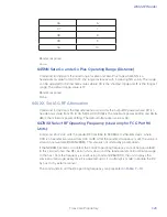
Страница 59: ...factory default setting is command 4100 which selects a separation of one ID Variable N specifies ID separation as shown in Table 7 6 Table 7 6 Unique ID Code Criteria Command Uniqueness Criteria 410...

Страница 60: ...e ID test Select Unique ID Code Criteria 410N commands IDs that do not pass the validation test are not reported For example command 4203 specifies that the same ID must be obtained from the RF module...

Страница 61: ...mode the reader transmits Wiegand formatted tag data through the Wiegand interface and ASCII data the reader accepts reader commands and responds through the serial port interface The reader outputs d...

Страница 62: ...ti tag sort should be disabled 456 Enable eGo Plus Tag Initialization During Multi tag Sort Factory Default Command 456 enables the reader to send the eGo Plus Tag initialize command as part of the mu...

Страница 63: ...he reader is programmed to read this tag protocol 486Disable IAG Command 486 disables the reader from reading IAG protocol data from tags 487Enable IAG Command 487 enables the reader to read IAG proto...

Страница 64: ...ou set the information to any 20 character ASCII string desired using command 696S S Reader response An ASCII string from 1 to 20 characters in length 510 Display RF Transceiver FPGA Version Command 5...

Страница 65: ...ne delay Reader message MAIN B 2 to 7 S 0 to 1 P 0 to 2 D0 where B2 1200 baud B3 2400 baud B4 4800 baud B5 9600 baud factory default B6 19 2 kbps B7 38 4 kbps S0 one stop bit factory default S1 two st...

Страница 66: ...reader response is IDAP T0 D0 X0 indicating time date and auxiliary information not appended 525 Display Communications Protocol Status Command 525 displays the status of command 61N Selected Communic...

Страница 67: ...to 3 D 0 to F where C0 Host controls outputs C1 Predefined output mode O0 Both outputs off O1 Output0 on O2 Output1 on O3 Both outputs on I0 Both inputs false I1 Input0 true I2 Input1 true I3 Both in...

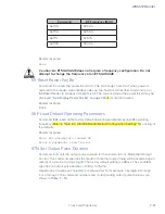
Страница 68: ...0 and input1 open closed conditions for the input status displays Table 7 10 Open Closed Conditions for Input Status Input Status Input0 Wire Pair Input1 Wire Pair Green Red Blue Black I0 Open Open I1...

Страница 69: ...r attenuation where 00 is maximum output power and 06 is minimum output power 6 dB less than maximum power For example if factory default settings are assigned the reader message is RFST C1 O0 T1 Fxx...

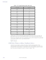
Страница 70: ...A2 RF off on timeout or presence condition false factory default T0 RF timeout of 0 ms always expired T1 4 ms T2 8 ms T3 12 ms T4 20 ms T5 24 ms T6 32 ms T7 48 ms T8 60 ms T9 92 ms TA 152 ms TB 300 m...

Страница 71: ...3 Four ID separations U4 Transmit all IDs V0 Valid ID code criteria of one acquisition V1 Valid ID code criteria of two acquisitions V2 Valid ID code criteria of three acquisitions V3 Valid ID code cr...

Страница 72: ...slation Mode Status Command 534 displays tag translation mode status enabled or disabled If tag translation mode is enabled incoming full frame tags in AAR or ATA format are translated according to IS...

Страница 73: ...rmatted similar to the data in the configuration command For example if the command string shown in command 697 refer to 697 Set User Programmable Group Select Equals GSE Filter on page 7 36 was sent...

Страница 74: ...isplays the synchronization values which are typically used to alleviate interference issues in dense populations of Interagency Group IAG readers The values are set with commands 648NN and 649NN Read...

Страница 75: ...on page 6 3 Reader response Done 6170 Disable Echo Mode Command 6170 disables the reader s echo of received host commands If operating in basic protocol or data inquiry protocol the reader echoes by...

Страница 76: ...ect Predefined Output Control Factory Default Command 621 configures the reader for predefined output mode In this mode output0 drives the RF Active LED and output1 is automatically asserted upon rece...

Страница 77: ...xadecimal value from 00 to 1F the range increases with increasing NN value The range can be adjusted for 32 discrete values where 00 is the shortest range and 1F is the longest range The default range...

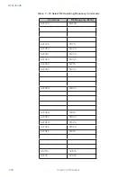
Страница 78: ...ng and 06 6 dB is the minimum power setting The default attenuation value is 04 647XXX Select RF Operating Frequency Used only for FCC Part 90 Units Command 647XXX sets the reader RF from 860 to 930 M...

Страница 79: ...erating Frequency Commands Command RF Frequency MHz 647000 860 00 6470CF 911 75 6470D0 912 00 6470D1 912 25 6470D2 912 50 6470D3 912 75 6470D4 913 00 6470EA 918 50 6470EB 918 75 6470EC 919 00 6470ED 9...

Страница 80: ...fault operating parameters except RF operating frequency Refer to Table 8 2 AI1422E Reader Default Configuration Settings for a listing of the defaults Reader response Done All parameters loaded OK Er...

Страница 81: ...command should be used with discretion For example when the tag acquisition interval is short compared to the selected pulse duration distinct pulses may not be generated Reader response Done or Erro...

Страница 82: ...timeout established by command 693N Set RF Timeout Period Command 6921 allows RF power to be turned off either after the timeout period or upon acquisition of a valid tag ID whichever occurs first The...

Страница 83: ...put is interpreted as an open circuit This feature allows greater flexibility in the attachment of external equipment to the reader inputs For example some proximity sensors indicate presence with an...

Страница 84: ...ddle character of the seven character number shown on the reader product label Note Once assigned the serial number is preserved during power down and the loading of default parameters Reader response...

Страница 85: ...s used for this comparison As an example to configure a reader to have only tags with data in byte locations 10 12 and 15 decimal with hexadecimal values 00 01 and 02 the following command is used 697...

Страница 86: ...nge on input0 822 Report change on input1 823 Report changes on input0 and input1 Reader response Done 830 Disable Automatic Periodic RF Status Report Factory Default Command 830 is a default set in t...

Страница 87: ...User Guide TransCore Proprietary 7 38...

Страница 88: ...8 Troubleshooting and Maintenance...

Страница 89: ...default by looping back the TX from the RS232 into the RX via a short wire Installing a loopback will cause the reader to reset its settings to factory default which is extremely useful during trouble...

Страница 90: ...e correct baud rate If an incorrect baud rate is suspected select and send each baud rate in turn using the 100x Baud Rate Select command and wait for a response Unit Will Not Read Tags The suggestion...

Страница 91: ...the RF frequency Refer to Radio Frequency on page 8 15 for instructions Error08 The RF PLL has successfully regained lock and has been reset to its proper operating frequency The RF section is returne...

Страница 92: ...will relate to symptoms configuration model and tags used Note End users and facility operators contacting Technical Support will be referred to the dealer responsible for the system sale Error Messag...

Страница 93: ......

Страница 94: ...Character Conversion A...

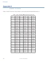
Страница 95: ...000010 8 011000 N 101110 000011 9 011001 O 101111 000100 011010 P 110000 000101 011011 Q 110001 000110 011100 R 110010 000111 011101 S 110011 001000 011110 T 110100 001001 011111 U 110101 001010 1000...

Страница 96: ...B Technical Specifications...

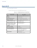
Страница 97: ...ting temperature 40 F to 158 F 40 C to 70 C Power requirement 24V to 110VDC 25 watts maximum Available frequency range 902 928 MHz FCC 860 870 MHz ETSI Approved frequency range for Federal Communicati...

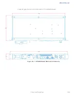
Страница 98: ...AI1422E Reader TransCore Proprietary B 3 Figure B 1 gives the mechanical dimensions of the AI1422E Reader Figure B 1 AI1422E Reader Mechanical Dimensions...

Страница 99: ......

Страница 100: ...C Lantronix Ethernet Module Configuration...

Страница 101: ...Port Redirector software which will allow connecting directly to the AI1422E through the Ethernet Interface from a Windows computer The Lantronix CPR software can be found at http ltxfaq custhelp com...

Страница 102: ...User Guide TransCore Proprietary C 2...

Отзывы: