AI1422E Reader
TransCore Proprietary
5-3
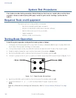
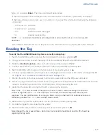
Type
!22
and press
Enter
.
The time and date will be returned.
If the time and date are not received, check communications connections, cycle power, and repeat.
If the time and date are incorrect, use
!20
and/or
!21
to correct this information, then type the following
commands:
!20hh:mm:ss
sets time
!21MM/DD/YY
sets date
!642
sets RF to follow the trigger
!41
enables tag reporting
NOTE:
!41
command should be used in diagnostic mode only. Do not use in normal system
operation.
The entered command and
!Done
response will be returned after each properly executed command.
Reading the Tag
To verify that the AI1422E Reader System is correctly reading tags:
1. Switch the ON/OFF switch located on the front panel of the reader system to
off
.
2. Using your own cable, connect the laptop PC to the reader system at the main RS232 interface.
3. Slide the
Interface Selection
switch on the front panel of the reader to RS232.
4. Connect the antenna to the antenna interface on the front panel of the reader system.
5. Set the ON/OFF switch located on the front panel of the reader system to
on
.
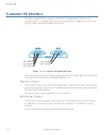
6. Connect a jumper between pins 14 (ground) and 15 (trigger) on the customer I/O interface to trigger the RF
on (
“Figure 3 – 3 Customer I/O Interface Pin-outs” on page 3-4
).
7. Monitor the LEDs on the box and verify that the main power LED and the RF power LED are lit.
8. Position a programmed TransCore half-frame rail tag with a backplate within 2 to 3 feet (0.6 to 0.9 m) of the
antenna. No other tag can be in this 2 to 3 foot (0.6 to 0.9 m) area during this test.
9. Verify that the lock LED is lit and that the PC is acquiring the tag data.
Note: If the
!41
command was issued prior to this test, the PC will be receiving a continuous
stream of tag data. If the
!41
command was not issued, the reader responds with only one
response. The Lock LED remains lit as long as there is a tag in the field, but only one response is
forthcoming unless the
!41
command has been issued.
10. Remove the tag from the antenna field. The PC should stop reading the tag data.
11. Disable the trigger by disconnecting the jumper.
12. Set the on/off switch located on the front panel of the reader system to
off.
Note: Repeat this test several times. Each time, the lock LED should be lit and the PC should be
reporting the tag data.
Содержание 1422E
Страница 16: ...Before You Begin 1...
Страница 20: ...AI1422E Reader TransCore Proprietary 1 5...
Страница 21: ...2 System Overview...
Страница 25: ...AI1422E Reader TransCore Proprietary 2 5 Figure 2 2 Antenna to Tag Centerline Tolerance...
Страница 26: ......
Страница 27: ...3 Interface Connections...
Страница 32: ...User Guide TransCore Proprietary 3 6...
Страница 33: ...4 Installation Instructions...
Страница 41: ...AI1422E Reader TransCore Proprietary 4 9...
Страница 42: ...5 System Test Procedures...
Страница 45: ......
Страница 46: ...6 Communications Protocols...
Страница 49: ......
Страница 50: ...7 Command Codes...
Страница 87: ...User Guide TransCore Proprietary 7 38...
Страница 88: ...8 Troubleshooting and Maintenance...
Страница 93: ......
Страница 94: ...Character Conversion A...
Страница 96: ...B Technical Specifications...
Страница 99: ......
Страница 100: ...C Lantronix Ethernet Module Configuration...
Страница 102: ...User Guide TransCore Proprietary C 2...

