VAV-SVP01A-EN
43
VAV VV550 Controller Programming and Operation
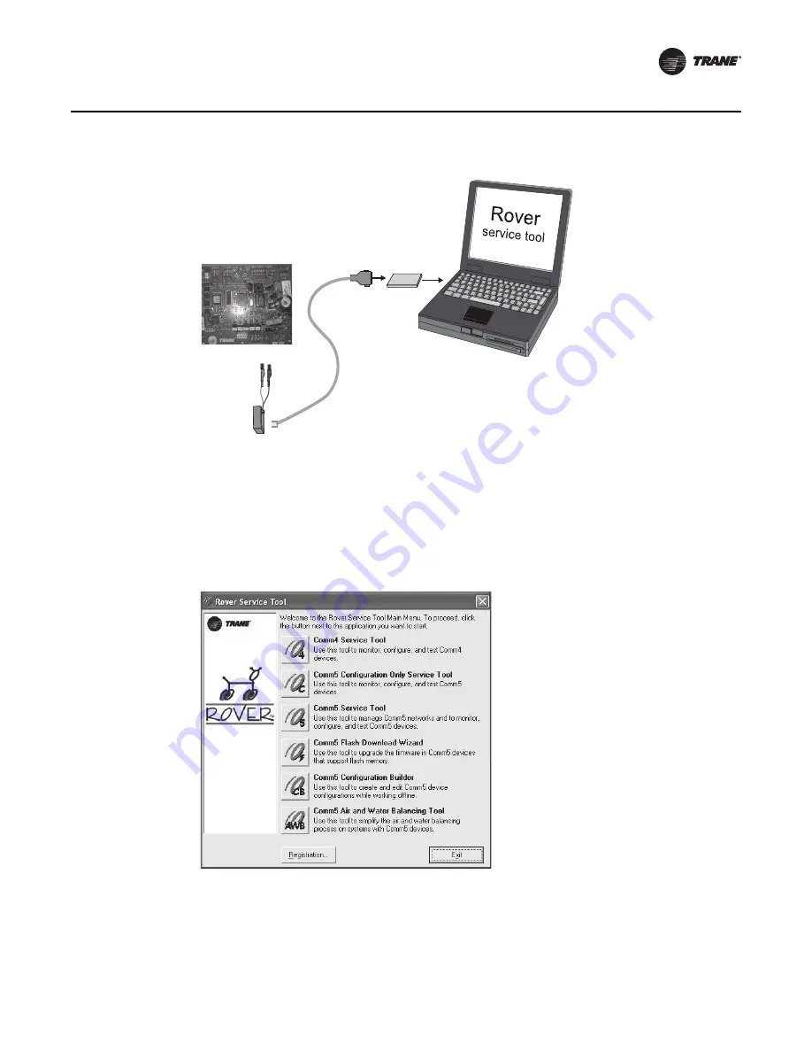
3. Double-click the Rover icon on the laptop PC desktop. The
Rover Service Tool
screen will
appear.
4. Double-click on the
Comm5 Configuration Only Service Tool
icon to access a Comm5
VV550. This tool allows the user to monitor, configure, and test Comm5 VV550 controller.
Note:
The configuration-only Rover Comm5 software runs only in the Passive mode. This means
that you can configure setpoints and other controller parameters but cannot create bindings
or set up peer-to-peer Comm5 networks. All other Rover Comm5 features are available.
5. Rover Comm5 will launch and the Rover service tool will automatically Scan for Neron ID of
Devices.
6. Once the scan is complete, the results will populate the device tree on the left-hand side of the
Rover Comm5 screen.
7.
Access the desired VAV VV550 Controller from the device tree.
Figure 31. Connecting to a Comm5 controller using alligator clips
Figure 32. Rover service tool
Comm5
PCMCIA card
Adapter
cable
RJ11 plug
Black
Red
Содержание VAV VV550 LonTalk
Страница 1: ...May 2010 VAV SVP01A EN Installation Operation Programming VAV VV550 LonTalk Controller...
Страница 17: ...VAV SVP01A EN 17 VAV Start Up Check Out Procedure Figure 2 VV550 single duct control diagram...
Страница 18: ...18 VAV SVP01A EN VAV Start Up Check Out Procedure Figure 3 VV550 fan powered control diagram...
Страница 107: ...VAV SVP01A EN 107 Troubleshooting Figure 59 VV550 single duct control diagram...
Страница 108: ...108 VAV SVP01A EN Troubleshooting Figure 60 VV550 fan powered control diagram...
Страница 110: ...110 VAV SVP01A EN Troubleshooting Figure 62 Single duct with three phase voltage electric heat...
Страница 112: ...112 VAV SVP01A EN Troubleshooting Figure 64 SCR PSC fan powered with three phase voltage electric heat...
Страница 114: ...114 VAV SVP01A EN Troubleshooting Figure 66 ECM fan powered with three phase voltage electric heat...
Страница 115: ......


