Error deadband
CNT-SVX12C-EN
69
Error deadband
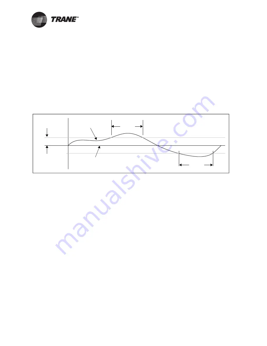
Error deadband is typically used to minimize actuator activity. It can also
be used to allow for some “slop” in the system sensors and actuator
mechanics. Error deadband prevents the PID output from changing if the
absolute value of the error is less than the error deadband. For example,
in Figure 26 the error deadband is set at 2.0°F (1.1°C). As long as the
absolute value of the error is less than the 2.0°F (1.1°C), the PID output
cannot change. If the absolute value of the error does exceed 2.0°F
(1.1°C), the PID output can change.
Figure 26. Error deadband
As can be seen from Figure 26, error deadband is a means of limiting how
often an actuator is controlled. If a PID loop controls a chilled water
valve, this is not so important. But if a PID loop controls how many stages
of cooling are being used, it is important to limit equipment cycling.
Adjusting error deadband for modulating outputs
In most applications, start with an error deadband of five or ten times the
sensor resolution. For example, thermistors have a resolution of approxi-
mately 0.1°F (0.06°C), so a good error deadband is 0.5°F (0.3°C). This set-
ting ensures that the sensor reading has changed an adequate amount
before the controller responds.
IMPORTANT
The error deadband should not be smaller than the sensor resolution or
the controller will react to noise.
Adjusting error deadband for staged outputs
This section shows how to adjust the error deadband for staging applica-
tions.
Finding the best error deadband for staged output applications is more
difficult than for modulating outputs. Instead of using a continuous actu-
ator, such as a chilled water valve, staged systems use binary outputs to
start and stop pieces of equipment, such as fans in a cooling tower. Each
Control
Control
Setpoint
Process
variable
Error deadband
Er
ror
Содержание Tracer ZN517
Страница 1: ...CNT SVX12C EN Installation and Operation Tracer ZN517 Unitary Controller...
Страница 2: ......
Страница 3: ...Installation and Operation Tracer ZN517 Unitary Controller CNT SVX12C EN April 2005...
Страница 4: ......
Страница 12: ...Table of contents vi CNT SVX12C EN...
Страница 38: ...Chapter 4 Sequence of operations for the 2 heat 2 cool configuration 26 CNT SVX12C EN...
Страница 56: ...Chapter 6 Sequence of operations for the 4 cool configuration 44 CNT SVX12C EN...
Страница 92: ...Chapter 10 Status indicators for operation and communication 80 CNT SVX12C EN...
Страница 104: ...Chapter 12 Troubleshooting 92 CNT SVX12C EN...
Страница 110: ...Index 98 CNT SVX12C EN...


