© 2008 - 2011 TOSHIBA TEC CORPORATION All rights reserved
e-STUDIO2020C/2330C/2820C/2830C/3520C/3530C/4520C
CONTENTS
5
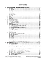
7.2 Precautions, Procedures and Settings for Replacing PC Boards and HDD ...................... 7-15
7.2.1 Precautions when replacing PC boards ................................................................. 7-15
7.2.2 HDD fault diagnosis................................................................................................ 7-16
7.2.3 Precautions and procedures when replacing the HDD........................................... 7-18
7.2.4 Precautions and Procedures when replacing the SYS board ................................ 7-23
7.2.5 Procedures and settings when replacing the SLG board ...................................... 7-24
7.2.6 Precautions and procedure when replacing the SRAM board (for the SYS board) 7-25
7.2.7 Procedures and settings when replacing SRAM board (for LGC board)................ 7-29
7.2.8 Firmware confirmation after the PC board/HDD replacement ................................ 7-31
7.2.9 Electronic key re-registration using the one-time dongle........................................ 7-32
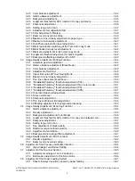
8.1.1 Master data/System ROM/Engine ROM/Scanner ROM........................................... 8-7
8.1.2 Imaging Acceleration Board ROM (GE-1170) ........................................................ 8-17
8.2.1 Writing the data to the download jig (PWA-DWNLD-350-JIG2) ............................. 8-24
8.2.2 System ROM .......................................................................................................... 8-27
8.2.3 Engine ROM ........................................................................................................... 8-29
8.3.1 Scanner ROM......................................................................................................... 8-33
8.3.2 RADF firmware (MR-3018)..................................................................................... 8-35
8.3.3 Finisher firmware (MJ-1101)................................................................................... 8-37
8.3.4 Converter Firmware (MJ-1101) .............................................................................. 8-39
8.3.5 Hole punch unit firmware (MJ-6101) ...................................................................... 8-43
8.3.6 Finisher firmware/Saddle stitcher firmware (MJ-1030) ........................................... 8-47
8.3.7 Finisher firmware (MJ-1031)................................................................................... 8-51
8.3.8 Fax unit firmware (GD-1250) .................................................................................. 8-54
8.4 Confirmation of the updated data ...................................................................................... 8-56
8.5 When Firmware Updating Fails ......................................................................................... 8-57
8.5.1 Procedure ............................................................................................................... 8-57
8.5.2 Flow chart for correcting USB update failure.......................................................... 8-58
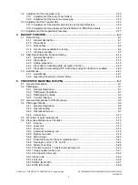
9.1 General description.............................................................................................................. 9-1
9.2 Construction......................................................................................................................... 9-1
9.3 Operation of DC Output Circuits .......................................................................................... 9-2
9.4 Output Channel ................................................................................................................... 9-3
9.5 Fuse..................................................................................................................................... 9-5
9.6 Configuration of Power Supply Unit..................................................................................... 9-6
9.7 Sequence of Power Supply ................................................................................................. 9-7
9.8 AC Wire Harness ................................................................................................................. 9-9
10. DC WIRE HARNESS / ELECTRIC PARTS LAYOUT................................................. 10-1
10.1 DC Wire Harness............................................................................................................... 10-1
10.2 Electric Parts Layout.......................................................................................................... 10-2


