Injection Molding Machine Chapter 6
V3.0
6-1
Chapter 6: Maintenance
Attention: Before doing any maintenance work
,
make sure the power supply is cut off.
1
Safety devices inspection
Upon machine starting
,
safety devices have to be inspected in detail thus ensuring the safety in machine
operation
,
safety devices are laid out as follows:
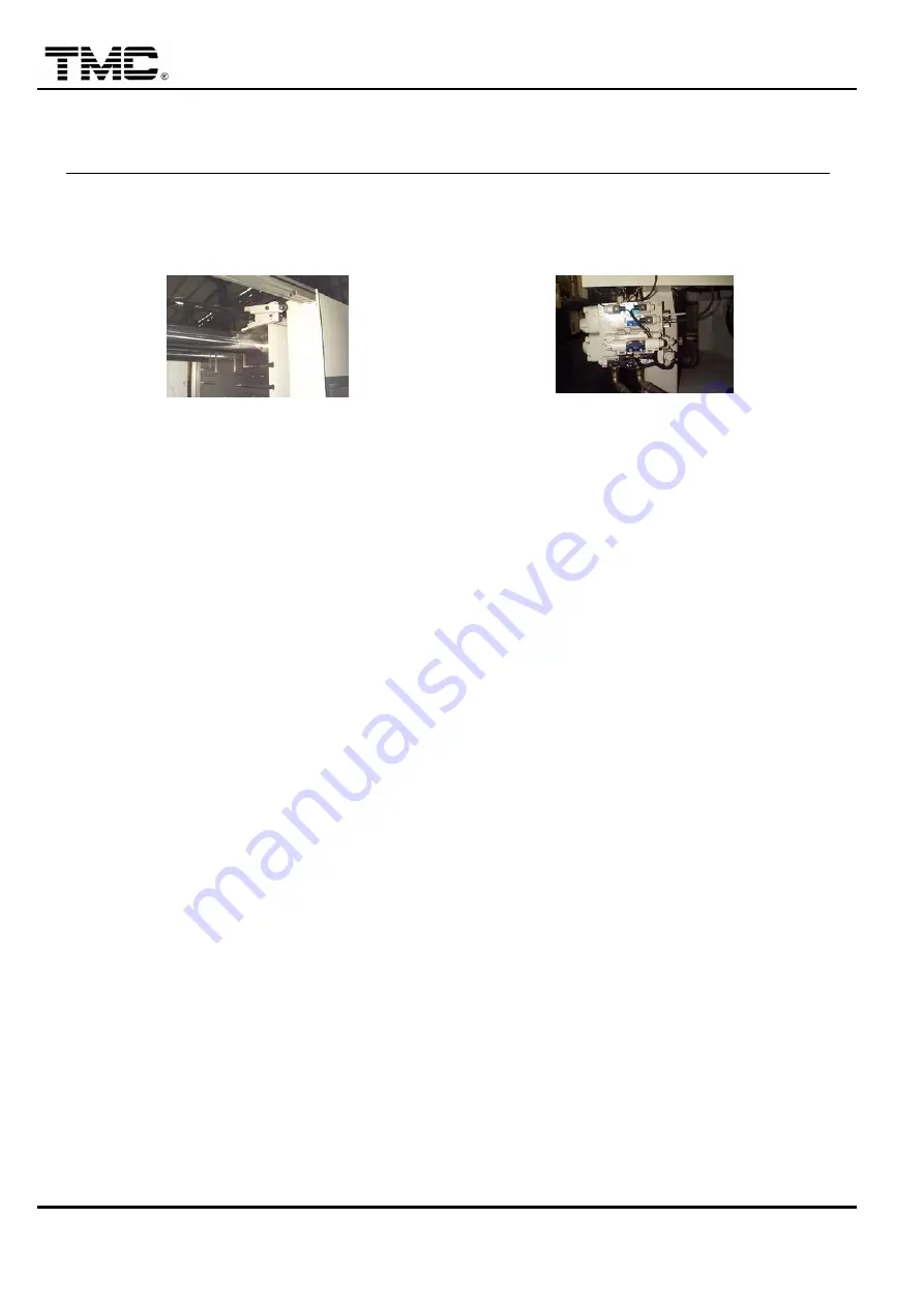
Drop bar and Scotch bar set
Hydraulic safety device
1.1 Electrical safety
LIMIT SWITCH controls front and rear safety gates
,
minimum and maximum mold thickness
,
and
inspection method is
:
A) Open front/rear safety door in clamp side
,
inspect I/O 101
,
103 on I/O monitor screen
,
they must be
off
(
no highlighted
)
,
open front/rear safety door in injection side
,
inspect I/O 201
,
202 on I/O monitor
screen
,
they must be off.
B) Activate limit switch of minimum/maximum mold thickness
,
inspect
I/O 111
(
min. mold thickness
),
I/O 112
(
max. mold thickness
)
on I/O monitor screen
,
when limit switch is depressed
,
highlight of
the corresponding I/O disappeared.
C) Open the clamp side gate
,
emergency stop circuit will actuate
,
highlight of I/O 221 disappears.
D) Press front or rear emergency stop button to activate emergency stop circuit
,
highlight of I/O 221
disappeared.
1.2 Hydraulic safety
The front/rear safety door interlocking circuits control V35 directional valve
,
and V35 controls the
hydraulic safety logic valve on the clamp manifold.
Methodsr inspection is
:
◇
When front or rear safety door is opened
,
clamp cannot be closed.
◇
Clamp cannot be closed with V35 unplugged.
1.3 Mechanical safety
Inspection methods for drop bar/scotch bar set
,
clamp safety guards
,
barrel guards are:
◇
Open front safety gate
,
the drop bar set will drop on the scotch bar.
Close front safety gate
,
the drop bar set will rise thus getting away from the scotch bar.
◇
Check tightness the fixing screw of clamp safety guards
,
barrel guards
,
etc.
Содержание TMC 1000E
Страница 20: ...Injection Molding Machine Chapter 2 2 4 V3 0 2 Machine dimensions ...
Страница 21: ...Injection Molding Machine Chapter 2 2 5 V3 0 3 Operating position ...
Страница 22: ...Injection Molding Machine Chapter 2 2 6 V3 0 4 Safety devices layouts ...
Страница 23: ...Injection Molding Machine Chapter 2 2 7 V3 0 5 Position of signs and labels ...
Страница 75: ...Injection Molding Machine Chapter 4 V3 0 4 32 starts running to cool down barrel ...
Страница 132: ...Injection Molding Machine Chapter 6 V3 0 6 11 4 3 Lubrication points and timing ...
Страница 136: ...Injection Molding Machine Chapter 6 V3 0 6 15 32 061 120 3141 Nozzle head S45C PCS 1 ...
Страница 148: ...Injection Molding Machine Appendix A A 3 V3 0 1 3 CARRIAGE ADVANCE If CARRIAGE MOVEMENT ON then CARRIAGE ADVANCE ...
Страница 149: ...Injection Molding Machine Appendix A A 4 V3 0 1 4 INJECTION INJECTION ...
Страница 150: ...Injection Molding Machine Appendix A A 5 V3 0 ...
Страница 151: ...Injection Molding Machine Appendix A A 6 V3 0 1 5 CHARGING ...
Страница 152: ...Injection Molding Machine Appendix A A 7 V3 0 If CARRIAGE MOVEMENT ON then CARRIAGE RETRACT ...
Страница 153: ...Injection Molding Machine Appendix A A 8 V3 0 1 6 CLAMP OPENING ...
Страница 159: ...Injection Molding Machine Appendix A A 14 V3 0 1 9 2 GAS VENT SEQUENCE ...
Страница 160: ...Injection Molding Machine Appendix A A 15 V3 0 1 9 3 INJECTION COMPRESSION SEQUENCE ...
Страница 161: ...Injection Molding Machine Appendix A A 16 V3 0 1 9 4 GAS VENT INJECTION COMPRESSION ...
Страница 168: ...Injection Molding Machine Appendix C C 0 V3 0 Appendix C Robot Connection 1 Signal Definition C 1 2 Wiring Example C 2 ...


