8-18
Application and Configuration Examples
Connection Diagram
Configuration
Carefully check all connections before entering these parameters.
1. Switch the AC Power to ON and verify:
•
Status LED is green. Refer to "Status indicator" on page 10-1 for an explanation of the dis-
play codes.
2. Start OMNI LINK on the PC.
3. Choose
Cancel
from the Drive Select dialog box.
4. Select
PC Set Up
from the Communications menu in OMNI LINK to display the personal com-
puter’s communication settings.
5. Verify the communications port settings of the PC match those of the drive.
•
If the settings are correct, select
OK
in the Port – Settings dialog box.
•
If the settings are different, correct the Port – Settings to allow communications with the
drive.
Factory default communications Port – Settings for the drive are:
– Baud Rate:
9600
– Data Bits:
8
– Parity:
None
Intro
F
IGURE
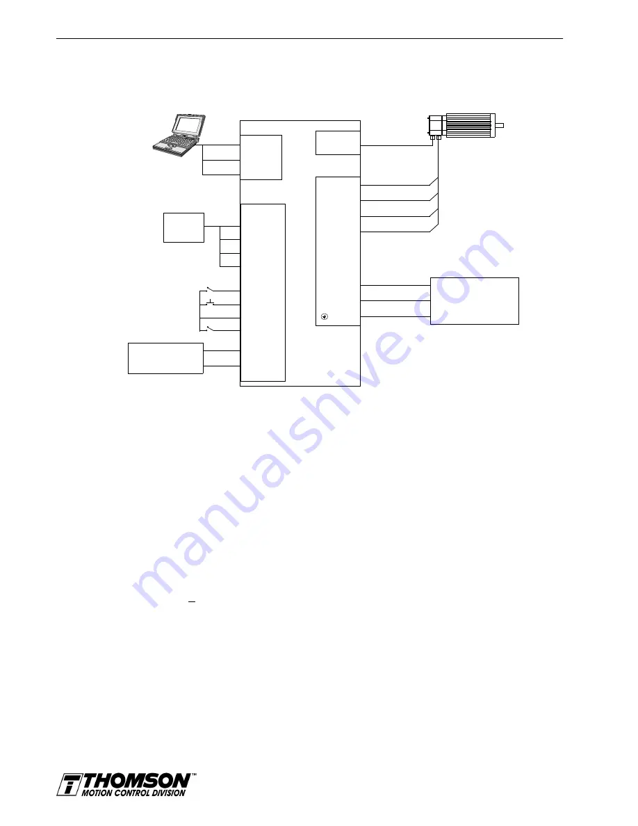
8.5
Step Up/Step Down Controller Connection Diagram
J1
14 CW+
15 CW-
16 CCW+
Close to ENABLE Drive
Close to RESET Fault
17 CCW-
Close to Follow
21 FAULT
26 I/O PWR
32 INPUT1
20 ENABLE
Step
Indexer
Note 1. Refer to Figure 6.23 - Figure 6.30 and for additional details on the Control Interface
DRIVE
L1 3
L2/N 4
Gnd 5
100-240 VAC
50/50 Hz
Single Phase
Power Source
RESET
TB1
Phase R 6
Phase S 7
Phase T 8
Mtr Gnd 9
J2
Motor
Encoder
External I/O
12-24 VDC
Power Source
5 I/O PWR
6 I/O COM
J5
2 RCV
3 XMT
5 COM
XMT
RCV
COM
Artisan Technology Group - Quality Instrumentation ... Guaranteed | (888) 88-SOURCE | www.artisantg.com


