


Specifications subject to change without notice.
94
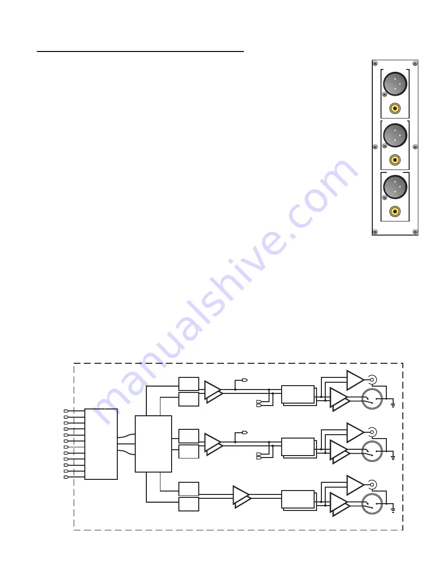
Superior II Balanced/Unbalanced D/A Output Card
Output Options:
Left, Right, Center.
Sub 1, Left Surround, Right Surround
Center, Left Back, Right Back
Sub 5, Left Back, Right Back
Sub 2, Left Surround, Right Surround
Sub 5, Left Surround, Right Surround
Sub 2, Sub 3, Sub 5 Sub 2, Left Back, Right Back
Sub 1, Left Back, Right Back Sub 2, Sub 3, Sub 4
Left, Right, Sub 1
Each output channel has a balanced (XLR) and a single-ended (RCA) output connector.
D/A Conversion:
24-bit Ladder (8X oversampling - 4x oversampling for 96KHz sources). Two DACs
per channel (6 per board) for true differential operation.
Volume Control:
Theta proprietary switched resistor network in the analog domain.
Digital Filter:
Theta proprietary FIR filter running on Motorola 56362 DSP.
Single-Ended Output:
Summed from balanced signals, retains many of the advantages of the balanced
output.
Sample Rates Supported:
32KHz, 44.1 KHz, 48 KHz, 88.1 KHz, 96 KHz.
Balanced Output Specifications:
Output Impedance:
20 Ohms.
Maximum Output Level: 20 V RMS.
Frequency Response: 20 Hz-20 kHz,
±
0.01 dB, Ref. 1KHz.
THD+Noise:
Less than 0.0016% @ 1KHz, maximum output level.
Dynamic Range:
105dB minimum, 20KHz bandwidth, Ref. 1KHZ, A-weighted.
Signal to Noise Ratio: 105dB typical, idle channel, A-weighted.
Crosstalk:
-90dB Right - Left, -120dB Center-Left @ 20KHz.
Single-Ended Output Specifications:
Output Impedance:
10 Ohms
Maximum Output Level: 10 V RMS
Frequency Response: 20 Hz-20 kHz,
±
0.01 dB, Ref. 1KHz.
THD+Noise:
Less than 0.0016% @ 1KHz, maximum output level.
Dynamic Range:
105dB minimum, 20KHz bandwidth, Ref. 1KHZ, A-weighted.
Signal to Noise Ratio: 105 typical, idle channel, A-weighted.
Crosstalk:
-90dB Right - Left, -120dB Center-Left @ 20KHz
Block Diagram:
TO TAPE
TO TAPE
ANALOG
DIRECT
L+
L-
OUT BUS
OUT BUS
LEVEL
CONTROLS
24 BIT
24 BIT
DAC
24 BIT
24 BIT
DAC
TO TAPE
TO TAPE
ANALOG
DIRECT
R+
R-
OUT BUS
OUT BUS
LEVEL
CONTROLS
24 BIT
24 BIT
DAC
24 BIT
24 BIT
DAC
56362
DIGITAL
SIGNAL
PROCESSOR
DIGITAL
SIGNAL
PROCESSOR
LEVEL
CONTROLS
24 BIT
24 BIT
DAC
24 BIT
24 BIT
DAC
DIGITAL
ROUTING
LOGIC
1
2
3
4
5
6
7
8
9
12
11
10
SUPERIOR II
SUPERIOR II
LEFT FRONT
LEFT FRONT
RIGHT FRONT
RIGHT FRONT
CENTER
Содержание Casablanca IV
Страница 2: ...THETA DIGITAL Casablanca IV Owner s Manual V 4 02 Digital Done Right...
Страница 11: ...10 Casablanca IV Block Diagram Input Processing Sections Figure 1 Input processing block diagram...
Страница 17: ...16 Figure 8 All Superior II D A Card Options...
Страница 19: ...18 Menu Maps Function Menus and Pages Figure 10 Mode Status Tape Out Menus and Input Select Pages...
Страница 20: ...19...
Страница 22: ...21...
Страница 31: ...30 Flowchart A Setup Subwoofer s...
Страница 32: ...31 Flowchart B Front Left Right Configuration...
Страница 33: ...32...
Страница 35: ...34 Flowchart F Setup Speaker Levels...
Страница 36: ...35 Flowchart H Setup Speaker Delays...
Страница 37: ...36 Flowchart I Setup Dolby Digital...
Страница 38: ...37 Flowchart J Setup DTS For 7 1 system Set additional Speaker Process Step 13h...
Страница 39: ...38 Flowchart K Copy Input Speaker Parameters...
Страница 40: ...39 Flowchart L Setup Default Mode...
Страница 41: ...40 Flowchart M Map Input Jacks...
Страница 42: ...41 Flowchart N Setup Analog Input Levels...
Страница 80: ...79 REMOTE CONTROL...
Страница 81: ...80 Figure 59 Remote Control Button Layout...
Страница 85: ...84 APPENDIXES...
Страница 88: ...87 Figure 62 Recommended Output Wiring Diagram Using 8 balanced Xtreme channels...
Страница 89: ...88 Six Shooter Wiring Diagram Figure 63 Wiring diagram for the optional Six Shooter...


