


14
Rear Panel Layout
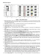
Figure 7 - Rear Panel Layout
1.
Main Power Switch.
Master power switch. Disconnects AC to all circuits. It is recommended that this be left ON
at all times during regular use, except when cables are connected/disconnected or when the unit will not be used
for an extended period of time.
2.
RS232
DB9, and RJ45 connectors. The DB9 is the preferred connector for external RS-232 control.
2a.
AC Power Connector
: 3 wire, IEC 320 connector with an EMI filter.
3.
USB Connector:
Preferred connector for firmware updates.
4.
Remote Power
jack. Activated/deactivated when associated front panel or remote button is pressed/pressed
again.
5.
Main Power 1
jack. Activated/deactivated when front panel
POWER
button is pressed/pressed again. All Main
Power jacks can output a 12V pulse (variable duration) or continuous 12VDC.
6.
Main Power 2
jack. Activated when front panel
POWER
button is pressed once, plus x seconds.
X
represents the
time value that is stored in the
SET-UP/GLOBAL/REM PWR/MTIM
parameter. This jack is deactivated when the
front panel
POWER
button is pressed again (putting the Casablanca IV in Standby mode).
7.
Main Power 3
jack. Activated when front panel
POWER
button is pressed once, plus two times
x
seconds.
X
represents the time value that is stored in the
SET-UP/GLOBAL/REM PWR/MTIM
parameter. This jack is
deactivated when the front panel
POWER
button is pressed again (putting the Casablanca IV in Standby mode).
8.
Remote Extender
jack. An externally mounted (remote) Infrared (IR) receiver plugs into this miniature stereo
phone jack. (Its signal must be demodulated). Please refer to Appendix C on page 89 for additional information.
9.
Power Supply Module
.
10.
HDMI Input/output card.
Accepts up to 4 HDMI 1.4 inputs (compatible with HDMI 1.1, 1.2, 1.3, etc.) Provides one
HDMI 1.4 output. Audio is processed within the Casablanca IV. Video is passed through untouched.
11.
Reserved for future use.
12.
Digital Input
card. This card provides one AES/EBU (balanced XLR) input, 4 each coaxial digital and Toslink
inputs, one each coaxial and TosLink outputs, one USB (Dirac/Software) connection There are two Volume Data
Out ports.
13.
Analog Input
card. Six stereo RCA inputs are provided for line level analog output devices such as VCR, laserdisc,
CD and DAT players, phono preamplifiers, external D/A converters, tape decks, AM/FM tuners, etc. There are two
pairs of analog tape outs for recording purposes, whose source can be selected in the
TAPE OUT
menu.
14. First
Analog Output
card. This slot could contain one of the following: A four-channel Xtreme D-2 quality DAC
(pictured), a four-channel Premium quality DAC card, or a 3-channel Superior II quality DAC card. The 3-channel
Superior II balanced cards also has single-ended outputs. The Xtreme D-2 card and the Premium card do not have
single-ended outputs. The channel sets that can be routed to a Superior II, Premium or Xtreme D-2 card (in any
DAC slot) are listed on pages 16 and 17 respectively, as well as in the specifications section of this manual.
15. Second
Analog Output
card. This slot could contain one of the following options: A four-channel Xtreme D-2
Содержание Casablanca IV
Страница 2: ...THETA DIGITAL Casablanca IV Owner s Manual V 4 02 Digital Done Right...
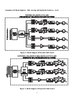
Страница 11: ...10 Casablanca IV Block Diagram Input Processing Sections Figure 1 Input processing block diagram...
Страница 17: ...16 Figure 8 All Superior II D A Card Options...
Страница 19: ...18 Menu Maps Function Menus and Pages Figure 10 Mode Status Tape Out Menus and Input Select Pages...
Страница 20: ...19...
Страница 22: ...21...
Страница 31: ...30 Flowchart A Setup Subwoofer s...
Страница 32: ...31 Flowchart B Front Left Right Configuration...
Страница 33: ...32...
Страница 35: ...34 Flowchart F Setup Speaker Levels...
Страница 36: ...35 Flowchart H Setup Speaker Delays...
Страница 37: ...36 Flowchart I Setup Dolby Digital...
Страница 38: ...37 Flowchart J Setup DTS For 7 1 system Set additional Speaker Process Step 13h...
Страница 39: ...38 Flowchart K Copy Input Speaker Parameters...
Страница 40: ...39 Flowchart L Setup Default Mode...
Страница 41: ...40 Flowchart M Map Input Jacks...
Страница 42: ...41 Flowchart N Setup Analog Input Levels...
Страница 80: ...79 REMOTE CONTROL...
Страница 81: ...80 Figure 59 Remote Control Button Layout...
Страница 85: ...84 APPENDIXES...
Страница 88: ...87 Figure 62 Recommended Output Wiring Diagram Using 8 balanced Xtreme channels...
Страница 89: ...88 Six Shooter Wiring Diagram Figure 63 Wiring diagram for the optional Six Shooter...


