


64
With Pro Logic IIx decoding, dominant center signals can come only from the
center speaker. The Center Width (
CWID
) control allows variable adjustment of
the center image so that it may be heard only from the center speaker; only from
the left/right speakers as a phantom image; or from all three front speakers to
varying degrees. The range is from 0 to 7. See figure 42b.
When all settings are made, pressing the
SETUP
button 2 times returns the user
to the
INPUT SELECT
menu.
Figure 42b – Diagram of Center Width Values
Содержание Casablanca IV
Страница 2: ...THETA DIGITAL Casablanca IV Owner s Manual V 4 02 Digital Done Right...
Страница 11: ...10 Casablanca IV Block Diagram Input Processing Sections Figure 1 Input processing block diagram...
Страница 17: ...16 Figure 8 All Superior II D A Card Options...
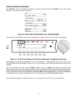
Страница 19: ...18 Menu Maps Function Menus and Pages Figure 10 Mode Status Tape Out Menus and Input Select Pages...
Страница 20: ...19...
Страница 22: ...21...
Страница 31: ...30 Flowchart A Setup Subwoofer s...
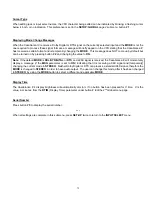
Страница 32: ...31 Flowchart B Front Left Right Configuration...
Страница 33: ...32...
Страница 35: ...34 Flowchart F Setup Speaker Levels...
Страница 36: ...35 Flowchart H Setup Speaker Delays...
Страница 37: ...36 Flowchart I Setup Dolby Digital...
Страница 38: ...37 Flowchart J Setup DTS For 7 1 system Set additional Speaker Process Step 13h...
Страница 39: ...38 Flowchart K Copy Input Speaker Parameters...
Страница 40: ...39 Flowchart L Setup Default Mode...
Страница 41: ...40 Flowchart M Map Input Jacks...
Страница 42: ...41 Flowchart N Setup Analog Input Levels...
Страница 80: ...79 REMOTE CONTROL...
Страница 81: ...80 Figure 59 Remote Control Button Layout...
Страница 85: ...84 APPENDIXES...
Страница 88: ...87 Figure 62 Recommended Output Wiring Diagram Using 8 balanced Xtreme channels...
Страница 89: ...88 Six Shooter Wiring Diagram Figure 63 Wiring diagram for the optional Six Shooter...


