


60
Default Mode
Each
INPUT SELECT
button can have a different default
MODE
assigned to it. To assign a default
MODE
for a given
INPUT SELECT
button, press the applicable
INPUT SELECT
button,
SETUP
/
INP
(input) then button #
4
(
MODE
). See
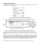
figure 16 on page 50. Edit this parameter to select the desired default
MODE
, then press
SETUP
twice to exit. Repeat
this procedure for each
INPUT SELECT
button.
Note
: Pressing the front panel
MODE
function button allows the user to audition different modes for a given source,
when applicable. Changing modes via the
MODE
button does not store a mode selection.
VFD Brightness
Each
INPUT SELECT
button can have a different VFD brightness assigned to it. Pressing button #
6
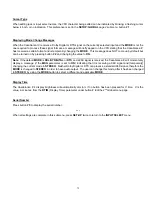
in figure 22 (page
50) allows the user to change the default brightness to
OFF, ¼, ½, ¾
or
FULL
brightness. Changes to this parameter
are reflected the next time that
INPUT SELECT
button is pressed. If this value is set to
OFF
, pressing any button except
DISPLAY
will automatically brighten the VFD to the maximum level. If the button pressed is not another
INPUT SELECT
or function button, then the VFD will revert back to its default brightness in
X
seconds.
X
represents the
TIME
parameter
value in the
SETUP
/
INP
Page 1
/ submenu. If the VFD is on but not set to
FULL
, it will remain at the default brightness
until a different
INPUT SELECT
button is selected. The
DISPLAY
button will override the default VFD brightness setting.
The
Display Time
feature takes precedent over the VFD brightness parameter. See details regarding the
Display Time
parameter on page 85.
Содержание Casablanca IV
Страница 2: ...THETA DIGITAL Casablanca IV Owner s Manual V 4 02 Digital Done Right...
Страница 11: ...10 Casablanca IV Block Diagram Input Processing Sections Figure 1 Input processing block diagram...
Страница 17: ...16 Figure 8 All Superior II D A Card Options...
Страница 19: ...18 Menu Maps Function Menus and Pages Figure 10 Mode Status Tape Out Menus and Input Select Pages...
Страница 20: ...19...
Страница 22: ...21...
Страница 31: ...30 Flowchart A Setup Subwoofer s...
Страница 32: ...31 Flowchart B Front Left Right Configuration...
Страница 33: ...32...
Страница 35: ...34 Flowchart F Setup Speaker Levels...
Страница 36: ...35 Flowchart H Setup Speaker Delays...
Страница 37: ...36 Flowchart I Setup Dolby Digital...
Страница 38: ...37 Flowchart J Setup DTS For 7 1 system Set additional Speaker Process Step 13h...
Страница 39: ...38 Flowchart K Copy Input Speaker Parameters...
Страница 40: ...39 Flowchart L Setup Default Mode...
Страница 41: ...40 Flowchart M Map Input Jacks...
Страница 42: ...41 Flowchart N Setup Analog Input Levels...
Страница 80: ...79 REMOTE CONTROL...
Страница 81: ...80 Figure 59 Remote Control Button Layout...
Страница 85: ...84 APPENDIXES...
Страница 88: ...87 Figure 62 Recommended Output Wiring Diagram Using 8 balanced Xtreme channels...
Страница 89: ...88 Six Shooter Wiring Diagram Figure 63 Wiring diagram for the optional Six Shooter...


