


13
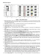
Front Panel Layout
Figure 6 - Front Panel Layout
1.
40 character by 2 row blue vacuum florescent display
(VFD).
2.
DISPLAY
button. Temporarily overrides the VFD brightness display setting in the
SETUP
/
INP
page 1 submenu.
3.
POWER
LED. Lights when the Casablanca IV is in standby mode.
4.
MAIN
POWER
button. After the rear panel
MAIN POWER
switch is turned on, press the front panel
POWER
button to exit
standby mode. The VFD will display the last selected
INPUT SELECT
menu. Pressing this button again will place the
Casablanca IV into standby mode and the LED above the front panel
POWER
button will light.
5.
REMOTE
POWER
button. Activates/deactivates the
REMOTE POWER
jack on the rear panel.
6.
Buttons
1
through
6.
Used to select a desired input on
INPUT SELECT
pages, or parameter to change when in a submenu.
The LED above the button lights when the button is pressed. These buttons are referred to as the
INPUT SELECT
buttons.
7.
MODE
button. Activates the
MODE
select menus for the currently selected input.
8.
TAPE OUT
button. Used for routing audio
INPUT
signals to the
TAPE OUT
jacks.
9.
SET-UP
button. Used for setting speaker configurations/levels/delays, analog input levels, naming inputs, setting the display &
remote power jack time-out delays, and accessing additional surround parameters, and all other
SETUP
functions.
10.
BALANCE
button. Sets temporary speaker balance configurations and analog input levels to compensate for different program
characteristics.
11.
A-D
button. Sequences through input jacks mapped (assigned) to the active
INPUT SELECT
button.
12.
MUTE
button. Mutes/unmutes all audio outputs with the exception of the
TAPE OUT
jacks.
13.
HDMI
indicator. Lights when the unit is turned on. It is one indicator that the unit accepts HDMI
14.
DOLBY TRUEHD
indicator
.
Lights when the unit is turned on. Shows that the unit processes Dolby’s lossless codec.
15.
DTS-HD MASTER AUDIO
indicator. Lights when the unit is turned on. Shows that the unit processes DTS lossless codec.
16.
DIRAC LIVE®
indicator. Illuminates when Dirac Live® digital room correction and optimization filters are in use.
17.
JITTER JAIL II™
indicator. Illuminates when Jitter Jail II jitter reduction circuitry is engaged.
18.
LOCK
light. Lights when a valid digital signal is detected on the selected input.
19.
LEVEL LEFT
and
RIGHT
buttons. Shifts audio balance to the left and right when the
BALANCE
function is selected, adjusts
the master volume within submenus when the
LEVEL UP
/
DOWN
buttons are to be used for parameter value editing, used to
toggle between the 2 input select pages, shifts to the next character when editing names.
20.
LEVEL UP
and
DOWN
buttons. Increases/decreases master volume. Also used to increment/decrement values in most edit
modes, and shifts
FRONT
/
REAR
audio balance in
BALANCE
submenu.
21.
1
through
6
LED indicators. Light when buttons
1
through
6
are selected.
Содержание Casablanca IV
Страница 2: ...THETA DIGITAL Casablanca IV Owner s Manual V 4 02 Digital Done Right...
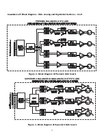
Страница 11: ...10 Casablanca IV Block Diagram Input Processing Sections Figure 1 Input processing block diagram...
Страница 17: ...16 Figure 8 All Superior II D A Card Options...
Страница 19: ...18 Menu Maps Function Menus and Pages Figure 10 Mode Status Tape Out Menus and Input Select Pages...
Страница 20: ...19...
Страница 22: ...21...
Страница 31: ...30 Flowchart A Setup Subwoofer s...
Страница 32: ...31 Flowchart B Front Left Right Configuration...
Страница 33: ...32...
Страница 35: ...34 Flowchart F Setup Speaker Levels...
Страница 36: ...35 Flowchart H Setup Speaker Delays...
Страница 37: ...36 Flowchart I Setup Dolby Digital...
Страница 38: ...37 Flowchart J Setup DTS For 7 1 system Set additional Speaker Process Step 13h...
Страница 39: ...38 Flowchart K Copy Input Speaker Parameters...
Страница 40: ...39 Flowchart L Setup Default Mode...
Страница 41: ...40 Flowchart M Map Input Jacks...
Страница 42: ...41 Flowchart N Setup Analog Input Levels...
Страница 80: ...79 REMOTE CONTROL...
Страница 81: ...80 Figure 59 Remote Control Button Layout...
Страница 85: ...84 APPENDIXES...
Страница 88: ...87 Figure 62 Recommended Output Wiring Diagram Using 8 balanced Xtreme channels...
Страница 89: ...88 Six Shooter Wiring Diagram Figure 63 Wiring diagram for the optional Six Shooter...


