


52
If the
#SUBS
4
, they will be assigned to Front L/R and Rear L/R. Each sub will get ¼ of the
LFE
. Additionally, the low
pass signal from any front speakers that are crossed over will be routed to the front subs (
SUB 1
and
SUB 2
) and the
low pass signal from any surround speakers that are crossed over will be routed to the surround subs (
SUB 3
and
SUB
4
). In this case,
SUB1
= Left Front Sub,
Sub2
= Right Front Sub,
Sub3
= Left Surround sub and
Sub4
= Right Surround
Sub.
If the
#SUBS
is
5
, each sub will get 1/5 of the
LFE
. The low pass signal from the front left/right speakers, if crossed
over, will be routed to the front left and right subs. If the center speaker is crossed over, its low pass signal will be routed
to the
SUB5
output. The low pass signal from any surround speakers that are crossed over will be routed to the left/right
surround subs.
Содержание Casablanca IV
Страница 2: ...THETA DIGITAL Casablanca IV Owner s Manual V 4 02 Digital Done Right...
Страница 11: ...10 Casablanca IV Block Diagram Input Processing Sections Figure 1 Input processing block diagram...
Страница 17: ...16 Figure 8 All Superior II D A Card Options...
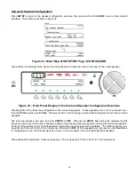
Страница 19: ...18 Menu Maps Function Menus and Pages Figure 10 Mode Status Tape Out Menus and Input Select Pages...
Страница 20: ...19...
Страница 22: ...21...
Страница 31: ...30 Flowchart A Setup Subwoofer s...
Страница 32: ...31 Flowchart B Front Left Right Configuration...
Страница 33: ...32...
Страница 35: ...34 Flowchart F Setup Speaker Levels...
Страница 36: ...35 Flowchart H Setup Speaker Delays...
Страница 37: ...36 Flowchart I Setup Dolby Digital...
Страница 38: ...37 Flowchart J Setup DTS For 7 1 system Set additional Speaker Process Step 13h...
Страница 39: ...38 Flowchart K Copy Input Speaker Parameters...
Страница 40: ...39 Flowchart L Setup Default Mode...
Страница 41: ...40 Flowchart M Map Input Jacks...
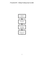
Страница 42: ...41 Flowchart N Setup Analog Input Levels...
Страница 80: ...79 REMOTE CONTROL...
Страница 81: ...80 Figure 59 Remote Control Button Layout...
Страница 85: ...84 APPENDIXES...
Страница 88: ...87 Figure 62 Recommended Output Wiring Diagram Using 8 balanced Xtreme channels...
Страница 89: ...88 Six Shooter Wiring Diagram Figure 63 Wiring diagram for the optional Six Shooter...


