


58
Internal Noise Generator
To aid in establishing a desired system speaker level balance, the Casablanca IV provides the user with the option of
routing the currently selected audio signal or an internally generated noise signal to a selected speaker.
This function is accessed via the
A-D
button in the
SETUP
/
INP
/
LVLS
submenu(s). Press buttons
1
-
6
to select a speaker.
Pressing the
A-D
button repeatedly toggles through these sources. Table 5 shows the 2 possible routings. When the
A-D
button is pressed, the source name or noise type will appear in the VFD below the submenu title.
Table 5 - Source to Output Routing for Speaker Level Configuration.
When use of the noise generator is complete, press
A-D
to once again re-route the
SOURCE
to the outputs.
Note
: It is recommended that levels be set relative to the Front Left and Right speakers. First adjust the Front Left and
Right level value(s) to zero dB. With the noise generator set to output to the left front speaker, adjust the master volume.
The remaining speakers can be adjusted accordingly by pressing buttons
2-6
one at a time, then pressing
LEVEL UP
or
LEVEL DOWN
to increase or decrease each speaker’s relative level using an SPL meter, until the desired system
balance is established. Please refer to the detailed
Step-by-Step Setup Guide
on page 23.
Note
:
Although speaker levels can be set using the internal noise generator as described
above. We recommend using a solution that includes the complete playback chain including
the blu-ray player and AIX test disc to set levels. Please refer to the detailed Step-by-Step
Setup Guide on page 24.
Press A-D Button
MODE
SOURCE USED
-
Selected Input
AUDIO INPUT
Once
Noise – one (selected) speaker
NOISE 1
Содержание Casablanca IV
Страница 2: ...THETA DIGITAL Casablanca IV Owner s Manual V 4 02 Digital Done Right...
Страница 11: ...10 Casablanca IV Block Diagram Input Processing Sections Figure 1 Input processing block diagram...
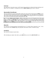
Страница 17: ...16 Figure 8 All Superior II D A Card Options...
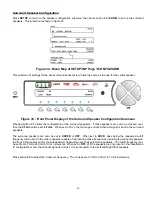
Страница 19: ...18 Menu Maps Function Menus and Pages Figure 10 Mode Status Tape Out Menus and Input Select Pages...
Страница 20: ...19...
Страница 22: ...21...
Страница 31: ...30 Flowchart A Setup Subwoofer s...
Страница 32: ...31 Flowchart B Front Left Right Configuration...
Страница 33: ...32...
Страница 35: ...34 Flowchart F Setup Speaker Levels...
Страница 36: ...35 Flowchart H Setup Speaker Delays...
Страница 37: ...36 Flowchart I Setup Dolby Digital...
Страница 38: ...37 Flowchart J Setup DTS For 7 1 system Set additional Speaker Process Step 13h...
Страница 39: ...38 Flowchart K Copy Input Speaker Parameters...
Страница 40: ...39 Flowchart L Setup Default Mode...
Страница 41: ...40 Flowchart M Map Input Jacks...
Страница 42: ...41 Flowchart N Setup Analog Input Levels...
Страница 80: ...79 REMOTE CONTROL...
Страница 81: ...80 Figure 59 Remote Control Button Layout...
Страница 85: ...84 APPENDIXES...
Страница 88: ...87 Figure 62 Recommended Output Wiring Diagram Using 8 balanced Xtreme channels...
Страница 89: ...88 Six Shooter Wiring Diagram Figure 63 Wiring diagram for the optional Six Shooter...


