


23
Overall Setup Procedure Flowchart
This flowchart shows all steps required to set up the Casablanca IV in order to achieve the best possible sonic
performance and to provide the simplest operation for all users. Follow solid and dotted lines to include Dirac Live® 96
kHz Room Correction and Optimization. Follow solid lines, only, to set-up without including Dirac Live® 96 kHz.
Instructions and detailed flowcharts for each step are contained on the following pages.
Figure 12: Casablanca IV Basic Set-up Flow Chart
Содержание Casablanca IV
Страница 2: ...THETA DIGITAL Casablanca IV Owner s Manual V 4 02 Digital Done Right...
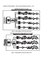
Страница 11: ...10 Casablanca IV Block Diagram Input Processing Sections Figure 1 Input processing block diagram...
Страница 17: ...16 Figure 8 All Superior II D A Card Options...
Страница 19: ...18 Menu Maps Function Menus and Pages Figure 10 Mode Status Tape Out Menus and Input Select Pages...
Страница 20: ...19...
Страница 22: ...21...
Страница 31: ...30 Flowchart A Setup Subwoofer s...
Страница 32: ...31 Flowchart B Front Left Right Configuration...
Страница 33: ...32...
Страница 35: ...34 Flowchart F Setup Speaker Levels...
Страница 36: ...35 Flowchart H Setup Speaker Delays...
Страница 37: ...36 Flowchart I Setup Dolby Digital...
Страница 38: ...37 Flowchart J Setup DTS For 7 1 system Set additional Speaker Process Step 13h...
Страница 39: ...38 Flowchart K Copy Input Speaker Parameters...
Страница 40: ...39 Flowchart L Setup Default Mode...
Страница 41: ...40 Flowchart M Map Input Jacks...
Страница 42: ...41 Flowchart N Setup Analog Input Levels...
Страница 80: ...79 REMOTE CONTROL...
Страница 81: ...80 Figure 59 Remote Control Button Layout...
Страница 85: ...84 APPENDIXES...
Страница 88: ...87 Figure 62 Recommended Output Wiring Diagram Using 8 balanced Xtreme channels...
Страница 89: ...88 Six Shooter Wiring Diagram Figure 63 Wiring diagram for the optional Six Shooter...


