Chapter 4: Parametric Graphing
93
Defining and Displaying Parametric Graphs
TI-84 Plus Graphing Mode Similarities
The steps for defining a parametric graph are similar to the steps for defining a function graph.
Chapter 4 assumes that you are familiar with Chapter 3: Function Graphing. Chapter 4 details
aspects of parametric graphing that differ from function graphing.
Setting Parametric Graphing Mode
To display the mode screen, press
z
. To graph parametric equations, you must select
parametric graphing mode before you enter window variables and before you enter the
components of parametric equations.
Displaying the Parametric Y= Editor
After selecting parametric graphing mode, press
o
to display the parametric Y= editor.
In this editor, you can display and enter both the X and Y components of up to six equations,
X1T
and
Y1T
through
X6T
and
Y6T
. Each is defined in terms of the independent variable
T
. A common
application of parametric graphs is graphing equations over time.
Selecting a Graph Style
The icons to the left of
X1T
through
X6T
represent the graph style of each parametric equation. The
default in parametric mode is
ç
(line), which connects plotted points. Line,
è
(thick),
ë
(path),
ì
(animate), and
í
(dot) styles are available for parametric graphing.
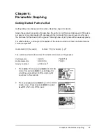
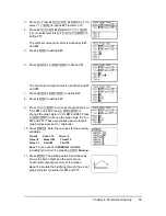
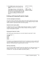
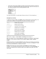
12. Press
r
to obtain numerical results and
answer the questions at the beginning of this
section.
Tracing begins at
Tmin
on the first parametric
equation (
X1T
and
Y1T
). As you press
~
to trace
the curve, the cursor follows the path of the ball
over time. The values for
X
(distance),
Y
(height),
and
T
(time) are displayed at the bottom of the
screen.

