B1
B1
A1
G
A2
B2
C1
C2
L1
K1
L2
K2
Links
Rechts
B1
D1
C1
A3
I3
G
EN
39
E
N
37878
05-2017
4
.
M
ai
n
te
n
an
ce
a
n
d
c
le
an
in
g
4.6
Trouble shooting
ã
Terberg Machines B.V., IJsselstein, The Netherlands
All rights reserved. No part of this book may be reproduced, stored in database or retrieval system, or published, in any form or in any way,
electronically, mechanically, by print, photoprint, microfilm or any other means without prior written permission from the publisher.
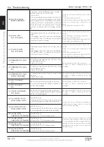
Trouble shoot diagram, electrical
Error
Check
Bin lift does not operate, no display text (display dark),
no green LED at N6 (bin security switch).
-
+24V at pin 1 and 2 of the 16-pin plug.
-
Fuses RCV supply pin 1 and pin 2.
Bin lift does not operate, display text
‘EMERGENCY STOP’.
-
All emergency stop switches on the vehicle.
-
+24V supply on pin 12 (normal safe situation) of
the 16-pin socket box.
Bin lift does not operate in automatic mode and/or
4-wheel container recognition does not operate.
-
If the ultrasonic sensors are free of dirt.
Bin lift does not operate, there is a certain alarm
message on the display.
-
Check the relevant alarm message in the list, see
the following pages.
Trouble shoot diagram, mechanical
Error
Check
Bin lift is losing bins/containers.
-
Check the bin/container locking mechanism for
refuse / obstructions.
-
Check the adjustment of the bin/container lock
(see also chapter 4.3).
Valve open diagram (only to be used if the electrical system works properly)
A1
B1
C1
K1
L1
A2
B2
C2
K2
L2
G
UP left
+
-
+
-
- +
-
-
-
-
-
-
DOWN left
-
+
+
- + + -
-
-
-
-
-
-
UP right
-
-
-
-
-
+
-
+
-
- +
-
DOWN right
-
-
-
-
-
-
+
+
- + + -
-
UP 4-wheel
+
-
+
-
- + +
-
+
-
- +
-
DOWN 4-wheel
-
+
+
- + + -
-
+
+
- + + -
-
+ -
= 50%
- +
Left
Right


