


Temperature Control Units : Veteran with LXG Series Instrument
Page: 56
TEMPTEK, INC.
525 East Stop 18 Road Greenwood, Indiana 46142
317-887-6352 Fax: 317-881-1277
Email: [email protected]
gearbox assembly is defective. To be certain, remove the motor as outlined
below, maintain the electrical connection and supply power to the instrument. If
the motor does not turn, the motor/gearbox should be replaced. If the motor does
turn, the operator can determine the valve assembly is defective.
2.
Valve assembly defective.
The valve assembly may become fouled with
process debris or the internal components may be defective.
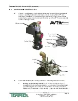
C.
The components of the AVT
TM
valve can be serviced separately.
To begin the AVT
TM
valve
service procedure, proceed with steps 1 - 5:
1.
Disengage process operations and verify all system pressure is relieved and the
unit’s pressure gauges read “0”.
2.
Disengage main power supply and verify the Power light on the display is “off”.
3.
Remove the lift-off access panel and set aside.
4.
Disconnect the valve wiring harness.
5.
Remove the AVT
TM
valve’s drip cover.
D.
To service the motor driver/gearbox components, continue with steps 6 - 12:
6.
The motor/gearbox assembly is mounted to the valve bracket and is secured by
2 mounting screws.
NOTE:
It will also be necessary to remove the 2 screws that secure the micro
switch to completely remove the motor since they are hard wired together.
7.
Remove the 2 mounting screws. The motor and gearbox will now be loose.
Carefully separate the motor/gearbox from the attached coupling from the valve
assembly.
8.
Align the motor/gearbox and coupling to the valve assembly.
9.
Align the motor/gearbox assembly mounting holes to the holes in the cooling
cylinder. Replace the 2 mounting screws and loosely install the microswitch
screws.
10.
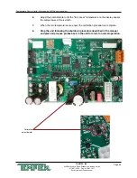
Reconnect the wiring harness. Home base is the reference point from which the
controller is able to open the valve incrementally. If the unit is not able to find
home, a valve fault “ULU” will appear in the Temperature display window. Adjust
the home switch to clear the fault.
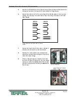
11.
Adjusting the home switch.
Apply power. The coupling should begin to turn.
When the lobe on the coupling is directly under the roller for the microswitch,
turn off the power. Adjust the microswitch so that the roller fully depresses the
microswitch. Turn on the power and the valve should turn forward and backwards
a few times and then stop at the home position. The valve light should be green
and you may begin operation. See diagram on next page.
Содержание Veteran VT LXG Series
Страница 2: ......
Страница 6: ...Page 6 THIS PAGE INTENTIONALLY BLANK ...
Страница 20: ...Page 20 THIS PAGE INTENTIONALLY BLANK ...
Страница 42: ...Page 42 THIS PAGE INTENTIONALLY BLANK ...
Страница 48: ...Page 48 THIS PAGE INTENTIONALLY BLANK ...
Страница 68: ...Page 68 THIS PAGE INTENTIONALLY BLANK ...
Страница 95: ...END 2021 TEMPTEK INC RE 20210323 ...
Страница 96: ......


