


Temperature Control Units : Veteran with LXG Series Instrument
Page: 62
TEMPTEK, INC.
525 East Stop 18 Road Greenwood, Indiana 46142
317-887-6352 Fax: 317-881-1277
Email: [email protected]
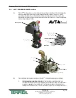
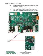
5.5 SENSOR PROBE SERVICE
A.
The temperature probe is a temperature transducer. The transducer is embedded into
a bulb well, which is threaded into the tank. The transducer converts the temperature of
the water into a proportional current output, which the microprocessor controller reads,
displays, and bases it controlling functions. The gain is automatically calibrated within the
controller electronics, the zero adjustment potentiometer is located on the CPU.
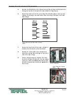
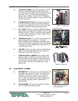
B.
Sensor probe errors are indicated by the Probe Fault screen.
When a sensor probe error is displayed, take the following steps
to correct:
1.
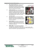
RECONNECTION.
If the service connection of the
sensor probe becomes saturated with water. Simply
unplug the connection, shake out the water to clear the
service connection and replug. If this was the problem, the error display should
change to Solid Red which can be cleared by pressing the Start push button. If
not, continue with replacement
.
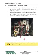
2.
REPLACEMENT
. Replacement of the sensor probe involves ceasing process
operations (as outlined in section 3.4 of this manual) and removing the defective
sensor probe. All factory supplied replacement probes are complete with the
service connection. Unit with ‘G’ Series instruments use one sensor probe. The
“high temperature limit” safety switch is a part of the sensor probe. To replace the
sensor probe, follow the procedure as outlined below:
a.
Stop process operations as described in
section 3.4
of this manual.
b.
Determine that all process pressure is relieved and the unit’s pressure
gauges read “0” pressure.
c.
Drain the unit by removing the pump casing drain plug. The unit can be
drained only to below the sensor probe mount if preferred.
d.
Disconnect the sensor probe service plug.
e.
Using a crescent wrench, remove the sensor probe from the cylinder. To
install a new sensor probe continue as follows:
f.
The new sensor probe threads should be lined with teflon tape and
coated with leak preventative sealant. Using a crescent wrench, thread
the new sensor into the machined boss of the cylinder.
g.
Reconnect the service connection. Restart the unit as outlined in
section
3
of this manual.
Sensor Probe Fault Screen.
Содержание Veteran VT LXG Series
Страница 2: ......
Страница 6: ...Page 6 THIS PAGE INTENTIONALLY BLANK ...
Страница 20: ...Page 20 THIS PAGE INTENTIONALLY BLANK ...
Страница 42: ...Page 42 THIS PAGE INTENTIONALLY BLANK ...
Страница 48: ...Page 48 THIS PAGE INTENTIONALLY BLANK ...
Страница 68: ...Page 68 THIS PAGE INTENTIONALLY BLANK ...
Страница 95: ...END 2021 TEMPTEK INC RE 20210323 ...
Страница 96: ......


