background image


Service Manual


7-9


Cleaning and Maintenance


7


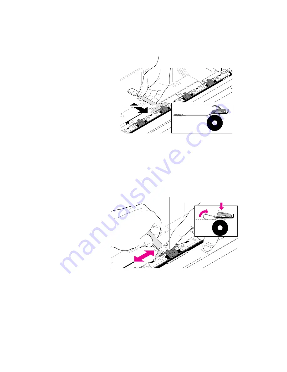
d.


Place the wide end of the cleaning pad (


foam side down


) on the 

platen beneath a paper clamp.  


e.


Gently press the clamp lever down with your finger to open 
the clamp.


f.


Slide the small end of the pad through the open clamp, wiping 
side-to-side.


g.


Repeat for all four clamps, then discard the cleaning pad.  

9d

9237-15

9e

9f

9237-16

Содержание Phaser 480

Страница 1: ...g The following servicing instructions are for use by qualified service personnel only To avoid personal injury do not perform any servicing other than that contained in operating instructions unless...

Страница 2: ...ble Tektronix Inc P O Box 1000 Wilsonville Oregon 97070 1000 Tektronix is a registered trademark of Tektronix Inc TekColor and Photofine are trademarks of Tektronix Inc Phaser is a trademark of Tektro...

Страница 3: ...For example a panel may cover the hazardous area Also applies to a hazard to property including the product itself DANGER A personal injury hazard exists in the area where you see the sign Care of pro...

Страница 4: ...ch exposed connections and components while power is on Disconnect power before removing the power supply shield soldering or replacing components Do not wear jewelry Remove jewelry prior to servicing...

Страница 5: ...care to repack it properly Failure to do so will result in damage to the printer 3 Remove the paper tray and repack it for shipping a Insert the two small foam shipping blocks into the paper tray on...

Страница 6: ...ack rubber belt to move the paper clamp bar so that it is positioned directly over the label Position paper clamp bar HERE to clear a paper jam b Insert the shipping block under the paper clamp bar c...

Страница 7: ...d with the posts upright or leaning slightly forward and facing outward as shown Caution The rubber cushions protect the printhead If they are positioned incorrectly the printhead will be damaged in s...

Страница 8: ...ser 480 Color Printer E Shipping the Printer 11 Repack the printer in the Tektronix shipping box Keep the printer level when moving 8849 50 Pha ser 48 0 ERRO R JAM MEDI A TRAN SFER ROLL COVE R READ Y...

Страница 9: ...inters This manual includes troubleshooting and adjustment procedures a field replaceable units FRU list and assembly disassembly procedures for selected FRUs To ensure complete understanding of the p...

Страница 10: ...s to serve customers with color pre press needs The Phaser 480X has the ability to create image separations and printing revealing overprinting and trapping information It also ships with improved col...

Страница 11: ...nto the paper to create its full gamut of color The printing paper is an ultra smooth material Since the transferred dye penetrates and bonds into the surface of the paper the prints are durable and d...

Страница 12: ...p cover Front panel Paper tray Power switch Left side Ph as er 48 0 ER RO R JAM ME DIA TRA NS FER RO LL CO VE R RE AD Y PO WE R 8849 03 Lo cal Ta lk Se ria l RS 23 2 Sta tus SC SI Pa ral lel PH AS ER...

Страница 13: ...l Information 1 Figure 1 4 Print with top cover open Figure 1 5 Print engine interior 8850 04 Thermal head Right side cover Top cover release Transfer roll 8849 05 Pinch roller Idle roller Timing belt...

Страница 14: ...switches locations 8850 06 Clutch B Upper transfer roll sensor Left step motor Clutch gear Exit sensor Right stepper motor Clutch F Clutch feed Paper size sensor Pick solenoid Paper clamp sensor Prin...

Страница 15: ...s with an installed sticker to place over the rear panel text not installed The TCP IP protocol is activated by a printer specific authorization code sold as a separate option Simply installing the Et...

Страница 16: ...th LED indicates the status of the printer s image processor board Blinking at a steady rate The printer is operating normally The LED blinks irregularly during diagnostics On or Off A hard error cond...

Страница 17: ...f blue to be less purple The switch change is effective immediately Switch down no color adjust If color correction is sent with the print job then this switch setting is ignored for that print job Re...

Страница 18: ...POWER Illuminates to indicate that the power supply is generating 5 VDC READY On indicates the printer is idle Blinking indicates the printer is receiving and processing data Off indicates that the p...

Страница 19: ...kgs 90 2 lbs Print engine paper tray and transfer roll weight only Table 1 4 Printer clearances Clearances Value Top 84 cm 33 ins Left 10 cm 4 ins Right 10 cm 4 ins Front Unrestricted to replace trays...

Страница 20: ...ack Transfer Roll features all black panels 650 A A4 B A3 or WB prints per roll Addressability 300 dots per inch 11 8 dots per mm horizontal and vertical Color addressability 8 bits per pixel 256 leve...

Страница 21: ...Part 15 Class B VDE 0871 6 78 Class B EN55022 CISPR 22 Class B VCCI CISPR 22 Class B Table 1 7 Environmental specifications Characteristic Specification Temperature Operating Non operating power off S...

Страница 22: ...22 2 No 950 Safety of Information Technology Equipment Including Electrical Business Equipment IEC 950 EN60 950 1988 Safety of Information Technology Equipment including Electrical Business Equipment...

Страница 23: ...as network system administration will be available for the scheduled installation and that all necessary cables will be available Unpacking This is the procedure for taking the printer out of its ship...

Страница 24: ...Protocols LocalTalk EtherTalk ThickNet 10Base5 TCP IP ThinNet 10Base2 Novell Twisted Pair 10BaseT other _______________ In the event that the printer is to be installed into a network environment wil...

Страница 25: ...to use with the printer Customers can purchase the following from the Tektronix Graphics Supplies Order Desk by calling 1 800 835 6100 10 ft parallel cable 012 1214 00 Serial 25 to 25 pin 3 m 10 ft nu...

Страница 26: ...S 5 0 or higher 2 Mbytes of hard disk space Workstation UNIX workstations The X Windows System SUN workstations OpenWindows recommended 750 kbyte hard disk space for files Based on the results of the...

Страница 27: ...rotocol support authorization key Option 16 add one 16 Mbyte RAM SIMM Option 32 add two 16 Mbyte RAM SIMMs Option L1 2 3 4 French Italian German or Spanish manual Option A1 2 3 5 International power c...

Страница 28: ...9 Phaser 480 User Manual 10 Phaser 480 Drivers and Utilities Printing Reference manual and diskettes 11 Optional Network Utilities for Phaser Color Printers manual and diskettes 12 Getting Started pa...

Страница 29: ...0 Co lor Pr inter U se r M a n u a l P h a se r 4 8 0 D r iv e r s a n d U ti li ti e s P r in ti n g R e fe r e n c e Ph aser 480 Dr ive rs an d Ut ilitie s Pr intin g Re fer en ce U se r M a n u a l...

Страница 30: ...Novell and TCP IP network protocols To determine if the option has been installed look for the Installed label above the Ethernet port If the label is there the option has been installed Also the net...

Страница 31: ...e of 1200 Switches 8 and 9 affect the printer s color output Switch 8 Down No Vivid Blue Adjust Up Vivid Blue adjust will change the way blue is printed it will look blue instead of purple This featur...

Страница 32: ...ith the printer powered off 2 For a LocalTalk network connection attach the network adapter to the printer s LocalTalk port Then attach the network cable LocalTalk cable PhoneNet etc to the network ad...

Страница 33: ...s serial port Attach the other end to the printer s serial port 3 Turn on the printer and the PC Networked connection to the PC using the Ethernet port In the Novell network the printer is connected...

Страница 34: ...connection to the workstation 1 Turn off the printer 2 In the case of an Ethernet network connect the interface cable to the printer s Ethernet AAUI connector You will need to use a network transceiv...

Страница 35: ...nting Reference for details on formatting the SCSI disk controlling sys start job files and using the LaserWriter Utility to load fonts onto the disk drive Figure 2 2 Connecting a SCSI hard disk drive...

Страница 36: ...bout the printer Fonts Ports Serial Parallel LocalTalk Ethernet EtherTalk Settings Serial Settings Pages Printed RAM Tektronix version firmware Adobe version software Ethernet address TCP IP authoriza...

Страница 37: ...bled and blue adjust Serial port settings Parallel port settings LocalTalk port settings EtherTalk settings TCP IP settings Novell settings Table 2 1 Configuration page settings for the Phaser 480 Par...

Страница 38: ...string 32 characters in length or less LocalTalk Node Indicates the LocalTalk network node number of the printer no 0 Any interger 0 through 254 Parallel Port interpreter Indicates the type of interp...

Страница 39: ...gin Password Indicates whether or not a network password has been set yes Not set Set Not set Queue Scan rate Rate at which printer will scan queue for print jobs yes 15 seconds An integer 1 through 3...

Страница 40: ...otal memory in the printer AppSocket port interpreter Indicates the type of interpreter in use at the System V configured port yes PostScript Level 2 Not Authorized Disabled PostScript Level 2 AppSock...

Страница 41: ...ng of 0 to 255 characters Trap Hosts A list of hosts one for each protocol which are able to receive traps yes None None N N N N Public N N N N Proxy N N N N Private N N N N Regional N N N N Core Priv...

Страница 42: ...ift key held down the message Extension off is displayed on the screen This disables any anti virus software 2 Place the Phaser Macintosh Printer Driver diskette into the disk drive 3 Double click on...

Страница 43: ...indows will have TekColor listed in their name Printers without this designation are using the standard Microsoft Windows PostScript driver and the WPD file 7 Type in the drive the PC diskette is in f...

Страница 44: ...ommunications ports You need to tell the driver which port your printer uses so the driver can print your documents The two main types of communications ports are parallel ports and serial ports your...

Страница 45: ...ch as 600 10 minutes to avoid the Alert message when printing multiple page documents 7 Choose the OK button to return to the Printers dialog box then choose the Setup button A dialog box appears with...

Страница 46: ...indows operation and terminology For additional information about Windows refer to your Microsoft Windows documentation Update procedure 1 Start Windows 2 Open the Control Panel 3 Double click on Prin...

Страница 47: ...heck existing printer object port assignments before installing a new printer to be sure there is no conflict Once you are familiar with existing printer objects drivers and ports associated with thes...

Страница 48: ...steps a Bring up the Settings Notebook by clicking the right mouse button on LPT2 PRINTER Click on the arrow to the right of OPEN click on SETTINGS b Select the Printer Driver Tab Confirm that the Tek...

Страница 49: ...cross print jobs and across power cycles they remain in effect until specifically changed again CTRL D systemdict languagelevel known languagelevel 2 eq true 0 startjob dup not exitserver errordict in...

Страница 50: ...tered exactly as shown 2 Use the DOS COPY command to send DEVPARAM PS to the printer for example COPY DEVPARAM PS COM1 Substitute the appropriate port for COM1 Table 2 2 Values for modifying the DEVPA...

Страница 51: ...ows Speed 9600 Flagging Software XON XOFF Data Bits 8 Parity Ignore To set up a printcap entry perform the following steps 1 Make a backup copy of the etc printcap file 2 Append to the printcap file a...

Страница 52: ...uld look like this bin sh bin cat 4 Give the if file executable permission chmod x if If communication to the serial port uses 7 data bits the value for xs changes as follows All other setup parameter...

Страница 53: ...me is TEKxxxxxx where xxxxxx is the last six hex digits of the printer s Ethernet address Select the printer If the printer is not displayed refer to the Novell Netware Configuration topic in the Netw...

Страница 54: ...ased with the printer For a TCP IP protocol field upgrade you will have to perform this procedure at the customer site This is done locally through the serial parallel or LocalTalk port 2 Set the prin...

Страница 55: ...item Network From its dialog box select the appropriate network port 1 Turn on the printer and the Macintosh if they are turned off 2 With the mouse click and hold on the Macintosh s Apple menu in th...

Страница 56: ...ubleshooting tips are included in the reference manual Phaser 480 Drivers and Utilities Printing Reference Guide Printing the directory from Macintosh 1 Make sure that you have an open window displaye...

Страница 57: ...A print dialog box appears on the screen Click on the Print button in the upper right corner of the dialog box to send a file to the printer If problems occur at this point download the error handling...

Страница 58: ...properly configured as explained in the Chapter 2 topic Cabling the printer on page 2 10 Windows 3 1 driver verification Using the Windows Paint application verify that the PC running under Windows 3...

Страница 59: ...available a You may print the contents of a window by pointing to that window and pressing Print Screen b You may print the full screen by first opening any window placing the cursor on the desktop aw...

Страница 60: ...here queue name is the name established by the network administrator of a queue the printer is to service such as SUB DYE L 1 specifies port LPT1 3 Use any text editor to create the following two line...

Страница 61: ...HSR480 directory on the Printer Utilities diskette 2 Copy the file TEKEHAND PS to the PC s hard disk or use the file from the diskette 3 Use the DOS COPY command to send the file to the printer For ex...

Страница 62: ...s site dependent and requires the aid of the site s network administrator Once the queue is in place you can proceed to the next step 3 Send a print file to the printer using the following syntax lpr...

Страница 63: ...es the aid of the site s network administrator Once the queue is in place you can proceed to the next step 1 To verify the host to Phaser 480 VMS host connection use the NCP LOOP CIRCUIT command from...

Страница 64: ...S file in the PHSR480 directory on the Printer Utilities diskette 2 Copy the file TEKEHAND PS to the workstation s hard disk or use the file from the diskette 3 Send the file to the printer This loads...

Страница 65: ...covers the last portion of the Tektronix Service Option S0 installation training the printer s key operator The steps you follow here place an emphasis on encouraging the key operator to read and use...

Страница 66: ...Error reporting Explain how error conditions are displayed on the front panel Show where error conditions are explained in the user manual Rear panel DIP switches Explain the functions of these switch...

Страница 67: ...magenta and yellow bands of the transfer roll handle it by the core endcaps only Fingerprints can affect print quality Demonstrate how to remove the transfer roll Show where handling the transfer rol...

Страница 68: ...that they could block the paper tray from being inserted into the printer Show how the pick rollers can be manually rotated into their proper position Print jam Show how you open the top cover to clea...

Страница 69: ...e printer as well as printer accessories such as software and printer stands that customers may be interested in United States Customers can call toll free at 1 800 835 6100 ask for the Supplies Order...

Страница 70: ...Hotline If customers encounter problems while using their printer they can call toll free at 1 800 835 6100 ask for the Customer Support Hotline The Hotline can answer technical question regarding us...

Страница 71: ...rovides a high level description of the sublimation dye printing technology and how the printer employs it Following that is a high level discussion of the image processor board and how it receives da...

Страница 72: ...to two main parts the print engine and the image processor The following topics describe these two parts in detail Figure 5 1 Functional block diagram 8850 11 Front panel board Host computer Engine bo...

Страница 73: ...the paper The thermal head is an electrical device containing 3576 individually controlled heating elements aligned parallel to the short axis of the paper it prints upon And because the row of therm...

Страница 74: ...e into seeing an intermediate color the dye sublimation printer can print that actual color with a single dot Because no dithering is used and the printer can create continuous tone colors the printer...

Страница 75: ...er the print engine prints only the colors cyan magenta and yellow and black However these colors called primary colors can be mixed together to simulate other colors called secondary colors When tiny...

Страница 76: ...outes received data signals to the data controller Thermal Head controller Each thermal heating element must receive sufficient energy to sublime dye properly Too much energy and the dot smears when p...

Страница 77: ...t segments from eight heating segments of the thermal head Individual elements in the segments may or may not be energized depending upon whether the element is to print a dot it is just that segments...

Страница 78: ...en The pick roller is positioned with the flat sides of its rollers facing down The paper feed guide is in its closed position against the feed roller The paper clamp guide is in its raised position T...

Страница 79: ...he print cycle begins the timing belts are driven backward to position the paper clamp bar in its clamping position over the clamp actuator roller Figure 5 4 The printing cycle paper clamp bar positio...

Страница 80: ...lowered Then the pick roller rotates to pick and drive a sheet of paper into the feed roller The feed roller aided by the feed roller guide in turn drives the paper into the paper clamp guide which d...

Страница 81: ...optically detects when paper has entered the paper clamp bar With the paper sensed in the clamp the clamp actuator roller is rotated so that the four spring loaded clamps close Figure 5 6 The printin...

Страница 82: ...s pulled completely out of the paper tray past the paper feed guide and the paper clamp guide and into the print path At this point the paper clamp guide moves up Note how the x axis tensioner lifts u...

Страница 83: ...movement of the paper moves the transfer roll As the paper and transfer roll move past the thermal head the thermal head selectively energizes its elements to transfer dye to the paper line by line fr...

Страница 84: ...he thermal head is raised to its standby position The pinch roller is also moved back to its standby position Then the paper advances in the paper path to a position that places the trailing edge of t...

Страница 85: ...to drive the print up the exit path The print is stopped when the paper clamp bar is in its paper pick position The clamp actuator roller then rotates to open the four clamps of the paper clamp bar F...

Страница 86: ...t roller then continues to rotate to drive the print up the exit path The rotating upper exit roller catches the print and continues to pull it through the exit path and into the output tray Figure 5...

Страница 87: ...Talk protocol The PostScript data received through the I O serializer is routed to the PostScript interpreter The PostScript interpreter generates display lists which describe objects and text fonts a...

Страница 88: ...the color plane data to the print engine The control loop also monitors the control and error signals fed back from the print engine Figure 5 12 The image processor graphics pipeline 8699 18 Image pr...

Страница 89: ...n the power switch is turned on 1 The front panel LEDs are lighted and remain on until the image processor board completes its self tests The POWER LED remains on all the time since it is wired to 5 V...

Страница 90: ...any test pattern using the Test Pattern Generator s four DIP switches and then press its print button 5 After the print is made remove the Test Pattern Generator If the printer prints a test pattern...

Страница 91: ...1 1 on This will hold the image processor in a state of reset 5 Turn on the printer and the print engine prints a test print If the printer does not power up go to the later topic Verifying power supp...

Страница 92: ...uitable power Inspecting the power supply fuses A fuse 15A 110 VAC or 6 3A 220 VAC is mounted into the power supply 1 Remove the lower rear cover to access the fuse 2 With a small flat blade screwdriv...

Страница 93: ...aper pick errors occur when the media in the paper tray mis picks or the printer double picks two sheets of paper 1 Clean the interior of the paper tray When installing paper push the stack of paper u...

Страница 94: ...Paper clamping failures can be caused by faulty sensors improper media size roller failure or poor media clamping Also check for foreign objects in the paper path 2 Ensure that the paper clamp bar ope...

Страница 95: ...media can get mistracked in the paper path 2 Examine the paper path Is there an obstacle blocking the path 3 Check to see if the paper clamp bar operates correctly Is it clean Paper or transparency f...

Страница 96: ...thermal head The ROM contains thermal head normalization data that compensates for the slight resistance variations from thermal head element to element Streaks or lines parallel to the short axis of...

Страница 97: ...ace the print engine Not printing The printer processes a sheet of paper but no image is printed on it 1 Ensure that the thermal head temperature is correctly set for the voltage value printed on the...

Страница 98: ...t they are undamaged and can activate the tray sensors Wrinkling Wrinkling occurs when the transfer roll is not maintaining smooth even contact between the thermal head and the paper instead it is wri...

Страница 99: ...cover open sensor plugs into J35 of the driver board Test the switch with an ohmmeter Head Cooling The thermal head has overheated wait and let it cool to see if error condition goes away Ensure that...

Страница 100: ...ch Table 6 3 Front panel error indications and solutions Error Solution Media tray indicates empty when it is not If there is media in the tray then check the media tray microswitches on the right sid...

Страница 101: ...ng to a black and white PostScript printer such as an Apple LaserWriter If the file does not print on the black and white PostScript printer this may mean that the problem may be application or networ...

Страница 102: ...ates the end of file which the printer responds to by closing host to printer communications and then processing and printing the file Use a text editor to open and examine the file Check and add if n...

Страница 103: ...are appearing purple To Access this option select Printer Setup Select Options Select Printer Features Select Vivid Blue under Color Correction This Tektronix Printer Options window can also be access...

Страница 104: ...or the printer returns to Ready mode without printing image For communication through the serial or parallel port Ensure that the print file ends with a CTRL D character CTRL D indicates the end of fi...

Страница 105: ...ft errors are errors that occur during the normal power up self test that while limiting the printer would not stop the printer from printing its startpage A message regarding the soft error would the...

Страница 106: ...sor s expansion memory or other options then the information is printed on the printer s startpage Normal power up tests take slightly longer than one minute to complete for a fully configured printer...

Страница 107: ...nformation regarding the information and setup values stored in NVRAM Refer to the topic The configuration page on page 2 15 Rear panel switches diagnostics Table 6 8 Image processor diagnostics rear...

Страница 108: ...the off position down 3 Power up the printer Wait for the printer s self test to complete 4 Observe the rear panel LED it begins flashing at a four flash per second rate for 10 seconds During the tim...

Страница 109: ...g elements 2 Open the top cover and wipe the surfaces of the black rubber rollers with an alcohol dampened cloth 3 Clean the pick rollers Users can either do this with an alcohol dampened lint free cl...

Страница 110: ...ed cloth gently clean the platen roller Use side to side strokes Rotate the platen as you clean it 7 Clean the transfer roll mark sensor s lenses with an alcohol dampened cloth Cleaning the printer 1...

Страница 111: ...alcohol at least 20 drops to the four sponges on the cleaning sheet Use a back and forth motion for the best coverage g Insert the paper tray into the printer Note The transfer roll must be installed...

Страница 112: ...t from the paper tray and put it away it can be used up to 12 times Wipe out any excess alcohol from inside the tray before refilling it with paper Put the paper tray back into the printer 3 Thermal H...

Страница 113: ...Do not exert much pressure on the thermal head 4 Separator Bar Wipe the edge of the separator bar 5 Paper Feed Roller a With the transfer roll tray removed open the gray plastic paper guide by graspi...

Страница 114: ...nd Idler Caution Avoid touching the rollers with your fingers oil from your hands can contaminate the rollers and can cause printing problems Use the lint free cloth moistened with 90 isopropyl alcoho...

Страница 115: ...h isopropyl alcohol against the rubber segments of the roller as you turn the green knob toward the back of the printer Make sure to clean both segments of the roller 8 Inside top cover and rack Using...

Страница 116: ...ing pads that were shipped with the cleaning kit a Use the black rubber belt to move the paper clamp bar b Position the paper clamp bar directly over the platen of the three rollers the platen is the...

Страница 117: ...ad foam side down on the platen beneath a paper clamp e Gently press the clamp lever down with your finger to open the clamp f Slide the small end of the pad through the open clamp wiping side to side...

Страница 118: ...cloth moistened with isopropyl alcohol When the tray is dry put the transfer roll back into the tray 11 Install the transfer roll tray Place the transfer roll tray back into the printer press down gen...

Страница 119: ...paper path and attract dust so apply lubrication sparingly Lubricate the following only when lubrication is needed Bushings Apply a drop of light oil to a bearing if it is noisy or running dry White...

Страница 120: ...cracked gears Belts Inspect the belts for wear There are three rubber belts in the printer a belt from the head motor to the head lift cam a belt from the drum motor to the drum pulley and a belt fro...

Страница 121: ...special handling or precautions Refer to Appendix A for a list of the printer s FRUs Required tools Magnetic tip screwdrivers 3 inch shaft and 6 inch shaft 1 POSIDRIV tip extended shank 003 0335 00 2...

Страница 122: ...city 2 Push the top cover release to open the top cover 3 Remove the two self tapping screws M4 x 16 which secure the top cover to the upper mechanical unit 4 Lift up on the top cover panel to disenga...

Страница 123: ...e printer and then backwards to remove Reverse these steps to reinstall the lower rear cover Figure 8 2 Removing the lower rear cover Lo cal Ta lk Se ria l RS 23 2 Sta tus SC SI Pa ral lel PH AS ER 48...

Страница 124: ...ne control board cover in place Reverse these steps to reinstall the engine control board cover Figure 8 3 Removing the engine control board cover Lo cal Ta lk Se ria l RS 23 2 Sta tus SC SI Pa ral le...

Страница 125: ...xplained in the previous procedure Lower rear cover on page 8 3 3 Slide the right rear cover rearward about 1 4 inch 6 mm 4 Lift the top edge of the cover so it clears the top cover release and pull t...

Страница 126: ...cover as explained in the previous procedure Lower rear cover on page 8 3 3 Slide the left rear cover rearward about 1 4 inch 6 mm 4 Lifting slightly on the upper edge of the left side cover pull the...

Страница 127: ...over on page 8 5 4 Remove the left side cover panel as explained in the previous procedure Left side cover on page 8 6 5 Remove the two screws M4 x 10 panhead securing the front cover in place 6 Reach...

Страница 128: ...free the thermal head at the left and right ends of the thermal head turn the release claws to unlock the thermal head Caution The thermal head is held under spring pressure In the next step be caref...

Страница 129: ...lign with the holes in the mounting bracket 3 Close the release claws to secure the thermal head in place 4 Install the two mounting bracket screws and washers removed earlier Thermal head ROM replace...

Страница 130: ...r covers on page 8 2 4 Open push back the gray plastic paper guide 5 Loosen the left side paper feed belt tensioner 6 Alter the feed roller s ring stopper from its extended position to its shortened p...

Страница 131: ...eft side of the printer Reverse these steps to reinstall the feed roller The bearings at each end of the roller must be fully seated for the ring stopper to fully extend and lock in the extended posit...

Страница 132: ...stic be careful not to break the pins at each end 5 At each end of the paper guide unlock the paper guide s holder by pushing down its locking hook while rotating the holder a 1 4 turn counter clockwi...

Страница 133: ...roller as explained in the earlier topic Feed roller on page 8 10 5 Remove the paper guide as explained in the earlier topic Paper guide on page 8 12 6 Alter the pick roller s ring stopper from its ex...

Страница 134: ...r in to the printer frame lift the right cam follower so it engages on the cam shaft as the pick roller is seated into position As you seat the pick roller lift and engage the left cam follower on its...

Страница 135: ...s Remove the board Reverse these steps to reinstall the engine control board When replacing the print engine control board be sure to transfer the printhead ROM M16 from the old board to the new board...

Страница 136: ...wiring harnesses and the ground wire connected to the power supply Also free the engine control board wiring harnesses secured to the power supply case 5 Remove the three screws M4 x 10 panhead secur...

Страница 137: ...board then you must transfer the RAM SIMMs and the network card to the new board You must also install all the parameters stored in the NVRAM chip of the old board into the NVRAM chip of the new board...

Страница 138: ...he SIMM Also a pawl on each end of the connector latches around each end of the SIMM to lock it in place Phaser 480X Locate the SIMM connectors J6 J7 and J8 Insert a keyed 32 Mbyte SIMM in connector J...

Страница 139: ...IMM in the Ethernet card connector J30 It could be damaged upon power up 5 Reinsert the image processor board into the printer 6 Turn on the printer and print a start page It lists the installed memor...

Страница 140: ...Disconnect all host computer interface cables connected to the printer 3 Remove the two screws securing the image processor board in place Carefully slide the image processor board out of the printer...

Страница 141: ...he Network Utilities for Phaser Color Printers User Manual explains how to activate the authorization code and download it to the printer Downloading the code depends on the available computers and ca...

Страница 142: ......

Страница 143: ...this chapter lists a series of steps you can follow to inspect and clean the printer you are servicing Required tools Magnetic tip screwdriver 3 inch shaft 6 inch shaft 1 POSIDRIV tip 2 POSIDRIV tip H...

Страница 144: ...eld in place by two screws M3 x 7 panhead 4 Disconnect wiring harnesses CN4 and CN5 from the top of the power supply 5 Flip DIP Switches 1 7 and 1 8 on Figure 9 1 Preparing the power supply for 24V ad...

Страница 145: ...to pin 5 of J11 24 V Connect the negative lead to pin 6 of J11 GND 7 Close the top cover plug in the printer s power cord and turn on the printer Figure 9 2 Connecting the voltmeter Ethernet Not Insta...

Страница 146: ...to match the value as labeled on the thermal head 9 After you make the adjustment remove the voltmeter and turn off the printer 10 Flip DIP Switch 1 7 and 1 8 down 11 Reconnect CN4 and CN5 Reinstall...

Страница 147: ...Connect the positive lead of the voltmeter to pin 1 of J11 5V Connect the negative lead to pin 4 of J11 GND 5 Close the top cover plug in the printer s power cord and turn on the printer 6 Measure th...

Страница 148: ...of the clamp bar using 90 pure isopropyl alcohol 3 Remove the top cover and the upper and lower rear covers as detailed in the Section 8 procedure The printer covers on page 8 2 4 Remove the engine c...

Страница 149: ...ned to yellow is referred to as X1 The distance cyan is misaligned to the right of yellow is referred to as X2 If the misalignment is over 140 make the appropriate following adjustment The vertical ye...

Страница 150: ...five sided F2 fixing plate 3 For X2 misalignment insert the gap gauge into the gap to the right of the fixing plate and the cross member it is attached to as illustrated in Figure 9 7 For X1 misalignm...

Страница 151: ...auge As you increase the thickness of the gap gauge the misregistration should be reduced 6 Once you have properly set the printer s registration Set DIP Switch 1 7 off and reinstall the printer s cov...

Страница 152: ...ws M3 x 7 panhead 5 Print a registration test print as explained in the Chapter 6 topic Verifying print engine operation by using its self test print on page 6 3 6 Examine the test print Look for yell...

Страница 153: ...n Table 9 1 DIP Switch 2 Adjusting vertical misregistration on paper on page 9 11 Figure 9 11 Vertical registration adjustment Table 9 1 DIP Switch 2 Adjusting vertical misregistration on paper Dip Sw...

Страница 154: ...Checks and Adjustments Table 9 2 DIP Switch 2 Adjusting vertical misregistration on transparency film Dip Switch 1 Length of yellow 5 6 7 color On Off Off Shorten Off On Off On On Off Off Off On On Of...

Страница 155: ...e units for the Phaser 480 and Phaser 480X color printers Changes to Tektronix instruments are made to accommodate improved components as they become available It is important when ordering parts to i...

Страница 156: ...00 1 LEFT SIDE COVER A 1 10 118 9126 00 1 RIGHT SIDE COVER A 1 11 118 9127 00 1 FRONT OUTPUT TRAY COVER A 1 12 118 9128 00 1 FRONT COVER A 1 13 118 9056 00 1 STACK SLIDE OUTPUT TRAY 159 0361 00 1 FUS...

Страница 157: ...Replaceable Units List A Figure A 1 The printer FRUs 8850 45A TYPE LOT NO 99 01 160 24 1V Ph as er 48 0 ERR OR JAM MED IA TRA NSF ER ROL L COV ER REA DY POW ER 1 2 23 4 3 15 14 7 6 9 12 5 10 11 8 25 2...

Страница 158: ...00 1 CLEANING KIT 006 3358 00 BAG OF 10 TEXWIPES 070 8849 00 1 USER MANUAL 070 8849 10 1 USER MANUAL FRENCH 070 8849 20 1 USER MANUAL ITALIAN 070 8849 30 1 USER MANUAL GERMAN 070 8849 40 1 USER MANUA...

Страница 159: ...t This appendix illustrates the test pattern produced by the print engine It also illustrates horizontal and vertical misconvergence Horizontal misconverg ence is misconvergence parallel to the printh...

Страница 160: ...ting 6 19 configuring a Novell server for the printer 2 31 configuring TCP IP 2 32 connecting the printer to the Macintosh 2 10 connecting the printer to the PC 2 11 connecting the printer to the work...

Страница 161: ...oving the printer E 1 N normal power up self test 6 18 Novell configuration 2 31 Novell Netware verification 3 6 null modem cable 2 29 O OS 2 connection verification 3 5 OS 2 Version 2 Tektronix drive...

Страница 162: ...d 6 10 printer does not print 6 9 printing is too light or too dark 6 9 streaks or lines in print 6 8 white portion of print is colored 6 8 Windows 6 15 workstations 6 16 wrinkled media 6 10 printing...

Страница 163: ...tor SCSI 2 13 Test Pattern Generator external 6 2 using D 1 thermal head 5 3 5 7 cleaning 7 4 thermal head fans 6 10 Timeouts Windows 2 23 transfer roll description 5 3 tray 7 3 7 5 transfer roll jam...

Страница 164: ...feed J32 J31 J35 J33 Driver card J34 J13 J16 J14 J13 Engine card J11 J19 J12 J59 CN5 24 V a CN4 24 V a CN3 24 V b CN1 5 V 24 V a 24 V b Power supply Thermal head unit I11 Right Left J16 J14 H12 CN2 24...

Страница 165: ...C 2 Phaser 480 Color Printer C Wiring Diagrams Figure C 2 illustrates a wiring routing diagram of the printer Figure C 2 Wiring routing diagram 8850 47...

Страница 166: ...tting up the printer 2 8 About installing RAM SIMMs 2 8 About installing an Ethernet card 2 8 Setting rear panel switches 2 9 Cabling the printer 2 10 Connecting the printer to the Macintosh 2 10 Loca...

Страница 167: ...and Host Connections Printing from a Macintosh 3 1 Selecting the printer via the Chooser 3 1 Printing the directory from Macintosh 3 2 Verifying that an application communicates to the printer 3 3 Usi...

Страница 168: ...4 Creating colors 5 5 Engine control board block description 5 6 CPU 5 6 Interface buffers 5 6 Thermal Head controller 5 6 Thermal head 5 7 Mechanical controller 5 7 The printing cycle 5 8 Idle 5 8 P...

Страница 169: ...ansfer roll jam 6 7 Printing and print quality problems 6 8 Streaks or lines parallel to the long axis of printing 6 8 Not printing 6 9 Printing too light or too dark 6 9 Image is offset or cut off 6...

Страница 170: ...allation 8 9 Thermal head ROM replacement 8 9 Feed roller 8 10 Paper guide 8 12 Pick roller 8 13 Engine control board 8 15 Power supply 8 16 Image processor board 8 17 RAM SIMM 8 18 Ethernet card 8 20...

Страница 171: ...x Phaser 480 Color Printer A Field Replaceable Units List B Test Pattern B Wiring Diagram D Test Pattern Generator E Shipping the Printer Index...

Страница 172: ...nting cycle paper clamp bar positioning 5 9 Figure 5 5 The printing cycle paper picking 5 10 Figure 5 6 The printing cycle paper clamping 5 11 Figure 5 7 The printing cycle paper loading 5 12 Figure 5...

Страница 173: ...2 Connecting the voltmeter 9 3 Figure 9 3 Adjusting 24V 9 4 Figure 9 4 Connecting the voltmeter 9 5 Figure 9 5 Inspecting the test print for misregistration 9 7 Figure 9 6 X1 and X2 misregistration 9...

Страница 174: ...Print engine power problems and solutions 6 12 Table 6 3 Front panel error indications and solutions 6 12 Table 6 4 Macintosh printing problems and solutions 6 13 Table 6 5 DOS printing problems and s...

Страница 175: ......

Страница 176: ...eceiving a file from a host computer In most cases the test patterns are generated by the printer s image processor and then printed by the print engine However in the case of a Phaser 480 printer the...

Страница 177: ...Pattern Generator while the printer is turned on 3 Press the Test Pattern Generator s START button Its green LED flashes as you press the button Figure D 1 Plugging theTest Pattern Generator into the...

Страница 178: ...terface To do so just select the appropriate DIP switch setting Table D 1 Test Pattern Generator DIP Switch settings Phaser 480 Pattern or function 1 2 3 4 5 7 vertical color bars On On On On On 7 hor...

Страница 179: ......

Отзывы: