background image

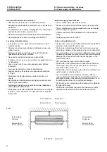
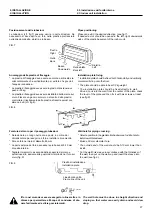
ATTENZIONE - E` importante che non cadano all'inter-
no dei tubi trucioli, polvere o altro perche` intasereb-
bero il circuito frigorifero all'altezza del capillare cau-
sando il blocco dell'impianto o il grippaggio del
compressore.

ATTENTION - It is important to prevent chips, dust or
other foreign bodes from dropping inside the pipes
since these would clog the refrigerating circuit at the
capillary causing the system to block or the compres-
sor to seize.

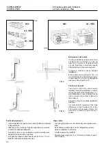
Connessione con le valvole.

* Rimuovere i dadi dalle tubazioni dell'unità interna.

* Rimuovere i tappi da entrambe le estremità delle tubazioni di 

collegamento.

* Rimuovere i dadi dalle tubazioni dell'unità esterna.

* Versare un po` di olio frigorifero sulle estremità cartellate 

delle tubature, quindi allineare le estremità cartellate alle 
uscite e fissare bene i dadi.

Connection to valves

* Remove nuts from the pipes of the indoor unit.

* Remove plugs from both ends of the connecting pipes.

* Remove nuts from the pipes of the oudoor unit.

* Drop some refrigerating oil onto the flare fittings of both ends 

of the pipes and tightly secure the nuts.

9. INSTALLAZIONE

9. INSTALLATION

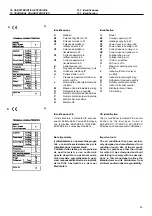
9.8. Spurgo aria

9.8. Air purging

Spurgo aria

L'aria e l'umidità che rimangono all'interno del

sistema di refrigerazione hanno i seguenti
effetti indesiderabili.

• La pressione nel impianto aumenta.
•  La corrente di esercizio aumenta.
•  L'efficienza refrigerante (o di riscaldamento)

diminuisce.

•  L'umidità nel circuito refrigerante può 

gelare e bloccare i tubicini capillari.

• L'acqua può portare a fenomeni di corrosione

dei componenti nell'impianto refrigerante.

Di conseguenza il gruppo interno e i tubi posti
tra gruppo interno e gruppo esterno devono
essere collaudati per perdite e spurgati per
rimuovere elementi non condensanti e umidità
dal sistema.

Spurgo aria con pompa a vuoto

Preparazione

Verificare che ciascun tubo (sia i tubi laterali
del gas che del liquido) tra gruppo interno e
gruppo esterno siano stati collegati nel modo
corretto e che tutti i cablaggi necessari al col-
laudo siano stati effettuati. Rimuovere i cap-
pucci delle valvole di servizio sia dai lati gas
che liquido sul gruppo esterno. Prendere nota
del fatto che a questo punto che ambedue le
valvole di servizio dei lati gas e liquido del
gruppo interno vengono mantenute chiuse.

Test perdite

•  Collegare la valvola manometro (con gli 

indicatori di pressione) ed la bombola del 
gas azoto all'apertura di servizio con i tubi di
carica.

Attenzione

Accertarsi di usare una valvola manometro
per lo spurgo d'aria. Se non è disponibile
usare una valvola di chiusura a questo scopo.
La manopola "Hi" della valvola manometro

Air purging

Air and moisture remaining in the refrigerant
system have undesirable effects as indicated
below.

•  Pressure in the system rises.
•  Operating current rises.
•  Cooling(or heating) efficiency drops.

•  Moisture in the refrigerant circuit may 

freeze and block capillary tubing.

•  Water may lead to corrosion of parts in 

the refrigeration system.

Therefore, the indoor unit and tubing between
the indoor and outdoor unit must be leak
tested and evacuated to remove any non con-
densable and moisture from the system.

Air purging with vacuum pump

Preparation

Check that each tube(both liquid and gas side
tubes) between the indoor and outdoor units
have been properly connected and all wiring
for the test run has been completed. Remove
the service valve caps from both the gas and
the liquid side on the outdoor unit. Note that
both the liquid and the gas side service valves
on the outdoor unit are kept closed at this
stage.

Leak test

•  Connect the manifold valve(with pres-

sure gauges) and dry nitrogen gas 
cylinder to this service port with charge 
hoses.

Caution

Be sure to use a manifold valve for air pur-
ging. If it is not available, use a stop valve for
this purpose. The "Hi" knob of the manifold
valve must always be kept close.

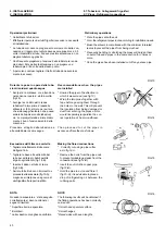
Indoor unit

Unità interna

Outdoor unit

Unità esterna

Valvola manometro

Manifold gauge

Indicatore di pressione

Pressure gauge

Tubo flessibile di carica

Charge hose

Bombola gas azoto 

(nella posizione verticale)

Nitrogen gas cylinder 

(in vertical position)

41

Содержание 2100x2 410A

Страница 1: ... I 410A 2650x2 410A 2600x3 3600 I 410A 2650 3600 410A 2650x3 410A 2650x2 3600 410A Questo manuale è stato creato per scopo informativo La ditta declina ogni responsabilità per i risultati di una progettazione o di una installazione basata sulle spiegazioni e le specifiche tecniche riportate in questo manuale E inoltre vietata la riproduzione anche parziale sotto qualsiasi forma dei testi e delle f...

Страница 2: ...opee 2002 96 CE e successive modifiche 2003 108 CE informandosi presso il Comune di residenza o presso il rivenditore nel caso in cui il prodotto venga sostituito con uno analogo Possible wasted electrical or electronic devices products should not be located together with normal domestic waste but disposed according to the current WEEE law in compliance with the European Directive 2002 96 EC and f...

Страница 3: ...HEAT FAN ONLY functions 23 3 4 4 Modalità AUTO DRY AUTO DRY operation 25 3 4 5 Esempi di programmazione timer Timer setting examples 25 4 Regolazione del flusso d aria 26 5 Funzionamento climatizzatore AUTO ECONOMIC DRY Temporanee Air Conditioner operation AUTO ECONOMIC DRY Temporary 27 6 Manutenzione Maintenance 6 1 Generale General 28 6 2 Pulizia del filtro Filter cleaning 27 7 Operazioni e pres...

Страница 4: ...2 ...

Страница 5: ...e risk of serious electrical shock never sprinkle or spill water or liquid on the unit ATTENZIONE Ventilare la stanza ogni tanto mentre il condizionatore è in funzione specialmente se ci sono altre apparecchiature a gas in uso nella stanza Non seguire questi consigli può causare una perdita di ossigeno nella stanza WARNING Ventilate the room occasionally while the air conditioner is in use especia...

Страница 6: ...eration Mantenere la temperatura della stanza a un livello confortevole Maintain room temperature at a comfortable level Pulizia del filtro dell aria Un filtro dell aria intasato riduce la poten za di raffreddamento Pulirlo ogni due set timane Clean air filter A clogged air filter reduce cooling effi ciency Clean it once two weeks Mai aprire porte e finestre oltre ciò che è necessario Per mantener...

Страница 7: ...ecomando a raggi infrarossi Remote control Alette regolazione flusso aria Horizontal air flow grille Cavo di alimentazione Power wire 5 2 COMPONENTI 2 COMPONENTS 2 1 Schema globale Selettori 2 1 Global view Switches Nella posizione AUTO la macchina è fuori dal controllo del telecomando funziona nella modalità ECONOMICA In AUTO position the unit will work in ECONOMIC mode without remote controlling...

Страница 8: ...o è attivata la funzione di con trollo dell aria calda 4 Indicatore di TEMPERATURA a Indica il valore impostato di temperatura Cambiando le impostazioni inizia a lampeggiare e si ferma dopo 20 secondi b Visualizza la temperatura ambiente quando il condiziona tore funziona in ventilazione FAN c Quando il condizionatore si ferma visualizza le impostazio ni di fabbrica d Visualizza i codici di protez...

Страница 9: ...are i segnali dal telecomando entro un raggio di 7 metri dal ricevitore dell unità interna Un avviso acustico du ne indica l avvenuta ricezione Se si seleziona la modalità TIMER il telecomando trasmette automatica mente il segnale all unità interna nell orario prefissato Se si tiene il telecomando in una posizione che ostacola la trasmissione del segnale può trascorrere un ritardo anche di 15 minu...

Страница 10: ...l lucernaio L angolo di oscillazione del lucernaio è 6 gradi ogni volta che si preme MODE select button 1 Push this button to select modes Each time you push the button a mode is selected in a sequence that goes from AUTO COOL DRY HEAT except cool only models FAN ONLY and back to AUTO ON OFF button 2 Push the button to start operation and push it again to stop When the air conditioner is restarted...

Страница 11: ... display digitale premerlo di nuovo per disattivarlo Pulsante CLEAN 15 Questo pulsante attiva il filtro pla sma lo ionizzatore o i raggi UV RESET button 7 When you push the RESET button all curent settings are cancelled and get into the beginning condition In the clock the colon in 0 00 will flash the mode displays AUTO the fan speed displays AUTO the temperatu re displays 24 C LOCK button 8 When ...

Страница 12: ...ton a fan speed is selected in a sequence that goes from AUTO LOW HIGH and back to AUTO Pulsante ON OFF ON OFF button 10 Pulsante O2 O2 button Attiva il generatore d ossigeno ove pre sente e fa variare la concentrazione di ossigeno nell ambiente Premere nuo vamente per disattivare la funzione Push this button to activate the oxygen generatinig mechanism if available and the oxygen density of indoo...

Страница 13: ...ore AUTO la temperatura 24 C When you push the RESET button all curent settings are cancelled and get into the beginning condition In the clock the colon in 0 00 will flash the mode displays AUTO the fan speed displays AUTO the tem perature displays 24 C Per bloccare le impostazioni correnti e il telecomando non accetta alcuna operazione se non quella relativa al pulsante LOCK Usare questa moda li...

Страница 14: ...ndirizzando il teleco mando verso il ricevitore Quando si riattiva il climatizzatore opera secondo le impostazioni pre cedenti Push the button to start operation and push it again to stop When the air conditioner is restarted it operates according to the last settings Pulsante FAN SPEED FAN SPEED button 3 3 TELECOMANDO R11 3 3 R11 REMOTE CONTROL 3 3 2 Funzioni a portellina chiusa 3 3 2 Functions w...

Страница 15: ...tion except the LOCK button one Use the lock mode when you want to cancel the clock mode Pulsante LOCK LOCK button Pulsante ECONOMIC RUNNING ECONOMIC RUNNING button Per impostare la modalità economica di funzionamento Push this button to set the economi cal operation mode Pulsanti TIMER ON OFF TIMER ON OFF buttons Premere il pulsante TIMER ON per impostare l orario di accensione Premere il pulsant...

Страница 16: ...ante POWERFULL POWERFULL button Per impostare l unità a piena potenza Push this button to set the powerfull mode Pulsanti TIMER ON OFF TIMER ON OFF buttons Premere il pulsante TIMER ON per impostare l orario di accensione Premere il pulsante TIMER OFF per impostare l orario di spegnimento Push the TIMER ON button to set the switch on time Push the TIMER OFF button to set the switch off time Pulsan...

Страница 17: ...s Indicatore LOCK LOCK display L icona compare quando si preme il pulsante LOCK Ripremendo il pul sante LOCK l icona scompare Displayed by pushing the LOCK button Disappears when the button is pushed again Indicatore FAN SPEED FAN SPEED display Mostra le diverse velocità del ventilatore selezionate possono essere visualizzati AUTO automatico e tre livelli di velocità LOW MED HIGH Compare AUTO quan...

Страница 18: ...te depending on which side you push If you push the button quickly the time will alter much quicker 2 OK button When you push the OK button the clock time display stops flashing and the clock starts operating 3 Readjusting the clock Push the CLOCK button in the battery compartment the colon in the clock display will start to flash To set the new time follow points 1 and 2 Clock accurancy is within...

Страница 19: ...gnere il climatizzatore Start Connect the unit to the power supply The OPERATION lamp on the dispay panel of the indoor unit starts flashing Operating in cooling heating fan mode 1 MODE select button Select between HEAT COOL FAN ONLY 2 Temperature button TEMP Set the desired temperature The optimal values are Cooling from 21 C up Heating from 28 C down 3 FAN SPEED button Push this button to select...

Страница 20: ...ory Thereafter the air conditioner will start operating under the same conditions when you simply push the ON OFF button of the remote controller Start The OPERATION lamp on the dispay panel of the indoor unit starts flashing 1 MODE select button Select AUTO 2 Temperature button TEMP Set the desired temperature Normally set it between 21 C to 28 C 3 ON OFF button Push this button to start the air ...

Страница 21: ...ith the ON OFF TIMER indicator and the colon in the timer setting will flash 2 Time adjust button TIME ADJUST Push to set the desired time forward backward Each time you push the button the time moves forward or back ward by 10 minutes depending on which side you push If you push the button quickly the time will change much quicker 3 Confirmation button OK Push this button and check whether the TI...

Страница 22: ...the set time Example To start the air conditioner at 06 00 1 Push the TIMER ON button 2 Use the TIME ADJUST button to display 06 00 on the remote control TIMER ON indicator 3 Push the OK button Programmazione combinata di spegnimento e accensione Acceso Spento Acceso Questa funzione è utile quando si desidera spegnere il climatizzatore dopo che si è andati a dormire e riaccenderlo quando ci si sve...

Страница 23: ... nad TIMER OFF no timer operation is performed Also the air conditioner may stop operating 1 Indicatore di trasmissione Transmission indicator L indicatore di trasmissione si accende ogni qualvolta il telecomando trasmette un segnale all unità interna This transmission indicator lights when remote control transmits signals to the indoor unit 2 Indicatore di modalita Mode display Mostra la modalità...

Страница 24: ...d and get into the beginning condition In the clock the colon in 0 00 will flash the mode displays AUTO the fan speed displays AUTO the tem perature displays 24 C 5 Pulsante ECONOMIC RUNNING ECONOMIC RUNNING button Per impostare la modalità economica di funzionamento Push this button to set the economi cal operation mode Per bloccare le impostazioni correnti e il telecomando non accetta alcuna ope...

Страница 25: ... 3 FAN SPEED button Push this button to select any of the AUTO LOW MED HIGH fan speeds 4 ON OFF button Push this button to start the air conditioner The OPERATION lamp on the display panel of the indoor unit lights The operating mode is selected in accordance with the room temperature and operation starts approximately after 3 minutes If FAN ONLY mode is selected the air conditioner starts imme di...

Страница 26: ...FF button of the remote controller Start 1 MODE select button Select AUTO 2 Temperature button TEMP Set the desired temperature Normally set it between 21 C to 28 C 3 ON OFF button Push this button to start the air conditioner The OPERATION lamp on the display panel of the indoor unit lights The operating mode is selected in accordance with the room temperature and operation starts approximately a...

Страница 27: ...visualizzare la temperatura Combined timer setting both TIMER OFF and ON Operation Stop Operation This feature is useful when you want to stop the air conditioner after you go to sleep and restart it when you wake up or you return back home The air conditioner will automatically stop and restart operating the set delays Example To stop the air conditioner in two hours time and restart it in ten ho...

Страница 28: ...To automatically swing the air flow direction Perform this function while the air conditioner is in operation Push the SWING button on the remote controller To stop the function push the SWING button again To change the swing direction push the AIR DIRECTION or SWING button repeatedly AVVERTENZE I pulsanti AIR DIRECTION e SWING sono disabilitati quando il climatizzatore non è attivo e quando è imp...

Страница 29: ...MIC DRY Temporanee AUTO ECONOMIC DRY Temporary Funzionamento ECONOMICO Se premete il pulsante ECONOMIC RUNNING durante il funzionamento in raffrescamento riscaldamento o automatico il climatizzatore effettua le seguenti operazioni La velocità del ventilatore viene controllata automati camente Nella zona in cui il funzio namento viene bloccato e la potenza ridotta al minimo un sovraraffredda mento ...

Страница 30: ...r 3 remove batteries from remote controller Controlli prima dell accensione Checks before operation AVVERTENZE Controllare che le connessioni a cartella non siano rotte o disconnesse Controllare che il filtro dell aria sia installato Controllare che l uscita e l entrata dell aria nell unità esterna non siano bloccate CAUTIONS Check that the flare wirings are not broken off or not connected Check t...

Страница 31: ...surriscalderà lo scambiatore del calore dell unità interna La lampadina PRE DEF è accesa durante questi intervalli indicando l operazione di preriscaldamento Controllo dell aria calda Quando la temperatura della stanza raggiunge il valore stabilito la velocità della ventola si riduce automaticamente per mantenere la temperatura raggiunta Allora l unità esterna si fermerà Sbrinamento Se l unità est...

Страница 32: ...ling Temp amb da 17 a 32 C Room temp 17 to 32 C ATTENZIONE Umidità relativa ambiente deve essere inferiore all 80 Se il condizionatore lavora sopra a questo limite la sua superficie può attirare la condensa CAUTION Room relative humidity less than 80 If the air conditioner operates in excess of this figure the surface of the air conditioner may attract condensation Riscaldamento Temp esterna da 5 ...

Страница 33: ... All accensione si nota un rumore dovuto all apertura delle alette Low noise of the air conditioner May be some ss sound caused by the flowing of refrigerant May be some zz sound caused by the natural expansion or shrinkage of plastic parts caused by temperature change At the starting may be some noise due to louvers turning Prima di domandare assistenza o riparazione controllare i seguenti punti ...

Страница 34: ... accensione il climatizzatore si attiva auto maticamente e l indicatore si spegne When the time set to start the air conditio ner is reached the air conditioner will automatically start and the appropriate indicator will go off Dirigere il trasmettitore del telecomando al ricevitore dell unità interna e poi premere due volte il pulsante ON OFF Direct the signal transmitter of the remote controller...

Страница 35: ...thorized personnel When installing the air conditioner wear suitable accident preventing garments such as goggIes gauntIets etc Work in absolute safety in clean surroundings free from impediments when installing the air conditioner Comply with the Iaws in force in the country where the air conditioner is installed in relation to use and disposal of pro ducts used to clean and service the appliance...

Страница 36: ...direct sunlight Position the unit in a place where condensate can be easily discharged and from whence the pipes can be easily connected to the outdoor unit Position the unit in compliance with a minimum distance from walls furniture or other see fig 1 Do not install the unit in workshops or kitchens where oil vapours mixed with the treated air could settle on the heat exchanger batteries thus red...

Страница 37: ...ina Install the outdoor unit in a sufficient ventilated sheltered place protected from the rain and direct sunlight Make sure that the point in which the unit is positioned is able to bearits weight and that vibrations and noise are not amplified Position the unit so that the air flow and noise do not disturb the neighbours There should be a distance all round between the unit and walls furniture ...

Страница 38: ...mportant to remember that if the difference in level between the indoor and outdoor unit exceeds3 meters it is essential to install a siphon every 3 meters Scelta delle tubazioni I tubi del liquido e del gas devono essere isolati termicamente e singolarmente Utilizzare un set di tubo per frigoristi reperibile in commercio e rivestito di materiale adeguato Le tubazioni da 5 m con isolamento e giunt...

Страница 39: ...the left right downwards sides of the plastic basement of the indoor unit Ancoraggio della piastra di fissaggio La piastra di fissaggio deve essere ancorata e allineata sia orizzontalmente che verticalmente per evitare che goccioli l acqua di condensa La piastra di fissaggio deve essere in grado di sostenere un peso di 50 kg La piastra di fissaggio deve essere installata direttamente sul muro Fiss...

Страница 40: ...are lo scarico Versare un bicchiere di acqua nell evaporatore Verificare che l acqua scorra attraverso il tubo flessibile di scarico del gruppo interno senza perdite e che fuoriesca dal l uscita dello scarico 4 Non togliere i tappi dalle tubazioni prima del collegamento Drain pipe installation Install the pipe units according to the position of the wall hole bind the drain hose to the pipes of the...

Страница 41: ...avi di alimentazione e di controllo tra unità interna ed esterna attraverso il foro del pannellino laterale Inserire i terminali del cavo di alimentazione nella morsettiera in accordo con i colori e i numeri corrispondenti fig 12 e fissare le viti Il filo giallo verde si collegacon la massa a terra Collegare il connettore del cavo di controllo al corrispondente connettore numerato nell unità ester...

Страница 42: ...e segue Reccomendations when the pipes are installed Unwind the pipe in the direction in which it was wound see fig 13 Wrap the two pipes together with tape before passing them through the holes in the wall This will prevent the insulation from being damaged or dust from entering the pipes as this would irreparably jeopardize the cor rect operation of he air conditioner Then proceeed to cut the pi...

Страница 43: ... nel modo corretto e che tutti i cablaggi necessari al col laudo siano stati effettuati Rimuovere i cap pucci delle valvole di servizio sia dai lati gas che liquido sul gruppo esterno Prendere nota del fatto che a questo punto che ambedue le valvole di servizio dei lati gas e liquido del gruppo interno vengono mantenute chiuse Test perdite Collegare la valvola manometro con gli indicatori di press...

Страница 44: ... la valvola a 2 vie girate lo stelo della valvola in senso antiorario di circa 90 aspettate 2 o 3 secondi circa e chiudetela Applicare l acqua saponata o liquido detergente neutro sui collegamenti dell unità interna o sui collegamenti dell unità esterna con una spazzola morbida per controllare eventuali perdite dei punti di raccordo delle tubature Dove c è fuoriuscita di bollicine vi è una perdita...

Страница 45: ...erante nell unità esterna open the valve Loosen the charge hose connected to the gas side service port slightly to release the pressure then remove the hose Replace the flare nut and its bonnet on the gas side service port and fasten the flare nut securely with an adjustable wrench This pro cess is very important to prevent leakage from the system Replace the valve caps at both gas and liquid side...

Страница 46: ...nto Collegamenti corretti dei cavi e delle tubazioni Perdite di gas dai collega menti delle tubazioni Valvole aperte completa mente I cavi di collegamentotra unità esterna ed interna sono inseriti in modo efficace nei terminali delle morsettiere Lo scarico è effettuato in maniera corretta La linea di terra è collegata in modo efficace L unità interna è fissata in modo sicuro Il voltaggio di alimen...

Страница 47: ...r outdoor noise level in dB A M Indoor outdoor weight in kg N Refrigerant type and quantity O Outdoor unit serial number P Indoor unit serial number Q Distributor brand name R CE marking R Q Identificazione CE Il climatizzatore è marcato CE secondo quanto dettato dalla Comunità Europea con le Direttive 89 392 CEE 73 23 CEE 89 336 CEE e successive modifiche Nota Importante Il climatizzatore è una m...

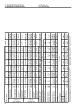
Страница 48: ...000 5 200 8 000 5 200 8 000 7 000 11 700 7 000 11 700 7 000 11 700 7 000 11 700 7 000 11 700 kcal h 4 470 6 880 4 470 6 880 4 470 6 880 6 020 10 060 6 020 10 060 6 020 10 060 6 020 10 060 6 020 10 060 BTU h 17 740 27 290 17 740 27 290 17 740 27 290 23 880 39 920 23 880 39 920 23 880 39 920 23 880 39 920 23 880 39 920 Watt 1 760 2 500 1 760 2 500 1 760 2 500 2 130 3 910 2 130 3 910 2 130 3 910 2 13...

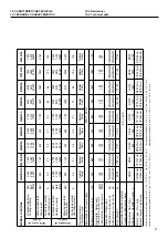
Страница 49: ... 64 R410A R410A R410A R410A R410A R410A R410A R410A R410A g 820 920 1 170 1 740 1 900 2 000 2 100 3 8 9 53 mm 1 2 12 7 mm 3 8 9 53 mm 3 8 9 53 mm 1 2 12 7 mm 1 2 12 7 mm 5 8 16 0 mm 5 8 16 0 mm 5 8 16 0 mm 1 4 6 35 mm 1 4 6 35 mm 1 4 6 35 mm 1 4 6 35 mm 1 4 6 35 mm 1 4 6 35 mm 3 8 9 53 mm 3 8 9 53 mm 3 8 9 53 mm Condizioni di prova raffrescamento int 27 C b s 19 5 C b u est 35 C b s 24 C b u Cooli...

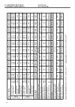
Страница 50: ...90 750x250x190 750x250x190 750x250x190 mm 760x590x285 760x590x285 760x590x285 845x695x335 895x860x330 895x655x345 895x655x345 895x655x345 860x830x330 860x830x330 kg 8 5 39 8 5 39 10 5 42 11 5 52 15 5 64 8 5 75 8 5 75 8 5 76 8 5 81 8 5 81 R410A R410A R410A R410A R410A R410A R410A R410A R410A R410A g 3 8 9 53 mm 3 8 9 53 mm 1 2 12 7 mm 1 2 12 7 mm 5 8 16 0 mm 3 8 9 53 mm 3 8 9 53 mm 3 8 9 53 mm 3 8 ...

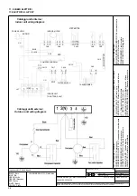
Страница 51: ...Condensatore compressore COMPRESSOR RELAY Relé compressore CURRENT DETECT Controllo assorbimento DISPLAY BOARD Scheda display FAN MOTOR Ventilatore unità esterna INDOOR MOTOR Motore ventilatore unità interna JX1 Terminal block Morsettiera MICROSWITCH Micro interruttore N NEUTRAL Morsetto neutro OXYGEN GENERATOR Arricchitore ossigeno OVERLOAD PROTECTOR Relé termico Klixon PIPE TEMPERATURE SENSOR Se...

Страница 52: ...OW GREEN Y G Giallo Verde BLUE Blu GREEN Verde ORANGE Arancione RED Rosso WHITE Bianco YELLOW Giallo AUTORESTART Circuito di auto restart CN Connectors Connettori DISPLAY BOARD Scheda display e ricevitore INDOOR FAN MOTOR Motore ventilatore unità interna INDOOR PCB JX Terminal block Morsettiera L Line Morsetto fase LOUVER MOTOR Motore alette MICROSWITCH Micro interruttore N Neutral Morsetto neutro...

Страница 53: ...u GREEN Verde ORANGE Arancione RED Rosso WHITE Bianco YELLOW Giallo AMBIENT SENSOR Sensori temperatura esterna e ambiente CN Connectors Connettori FILTER Filtro HEAT EXCHANGER SENSOR Outdoor Sensore temp con densatore JX Terminal block Morsettiera L Line Morsetto fase MODULE Modulo inverter N Neutral Morsetto neutro OLP TEMP SENSOR Sensore di temperatura OLP OUTDOOR FAN Ventilatore esterno OUTDOOR...

Страница 54: ...tori DISPLAY BOARD Scheda display e ricevitore EXHAUST SENSOR Dissipatore FILTER Filtro HEAT EXCHANGER SENSOR Outdoor Sensore temp condensatore INDOOR FAN MOTOR Motore ventilatore unità interna INDOOR PCB Scheda elettrnica unità interna IPM BOARD Inverter module Scheda modulazione inverter JX Terminal block Morsettiera L Line Morsetto fase LOUVER MOTOR Motore alette N Neutral Morsetto neutro OLP T...

Страница 55: ...ttori DISPLAY BOARD Scheda display e ricevitore EXHAUST SENSOR Dissipatore FILTER Filtro HEAT EXCHANGER SENSOR Outdoor Sensore temp condensatore INDOOR FAN MOTOR Motore ventilatore unità interna INDOOR PCB Scheda elettrnica unità interna IPM BOARD Inverter module Scheda modulazione inverter JX Terminal block Morsettiera L Line Morsetto fase LOUVER MOTOR Motore alette N Neutral Morsetto neutro OLP ...

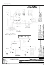
Страница 56: ...lay FAN MOTOR Ventilatore unità esterna FAN MOTOR CAPACITOR Condensatore ventilatore FOUR WAY VALVE Valvola a 4 vie INDOOR MOTOR Motore ventilatore unità interna JX1 Terminal block Morsettiera N NEUTRAL Morsetto neutro OVERLOAD PROTECTOR Relé termico Klixon PIPE TEMPERATURE SENSOR Sensore evaporatore POWER Alimentazione ROOM TEMPERATURE SENSOR Sensore ambiente STEP MOTOR Motore alette TRANSFORMER ...

Страница 57: ...blaggi unità interna Indoor unit wiring diagram CN Connectors Connettori COMPRESSOR Compressore COMPRESSOR CAPACITOR Condensatore compressore COMPRESSOR RELAY Relé compressore CURRENT DETECTOR Controllo assorbimento DISPLAY BOARD Scheda display FAN MOTOR Ventilatore unità esterna FAN MOTOR CAPACITOR Condensatore ventilatore FOUR WAY VALVE Valvola a 4 vie INDOOR MOTOR Motore ventilatore unità inter...

Страница 58: ...terna Indoor unit wiring diagram Cablaggi unità esterna Outdoor unit wiring diagram ANION GENERATOR Generatore ioni negativi CN Connectors Connettori COMPRESSOR Compressore COMPRESSOR CAPACITOR Condensatore compressore COMPRESSOR RELAY Relé compressore CURRENT DETECT Controllo assorbimento DISPLAY BOARD Scheda display FAN MOTOR Ventilatore unità esterna FAN CAPACITOR Condensatore ventilatore FOUR ...

Страница 59: ...aggi unità esterna Outdoor unit wiring diagram Cablaggi unità interna Indoor unit wiring diagram CN Connectors Connettori COMP Compressor Compressore CAP1 Compressor capacitor Condensatore compressore DISPLAY BOARD Scheda display FAN MOTOR Ventilatore unità esterna FAN 1 Indoor fan motor Ventilatore unità interna FAN 2 Outdoor fan motor Ventilatore unità esterna FAN CAPACITOR Condensatore ventilat...

Страница 60: ...Codice Code N Pezzi N Pieces Legenda colori Colours legend BLACK Nero YELLOW GREEN Y G Giallo Verde BLUE Blu GREEN Verde ORANGE Arancione RED Rosso WHITE Bianco YELLOW Giallo Cablaggi unità interna 2600 W 2600 W Indoor unit wiring diagram CN CZ Connectors Connettori CONTROL BOARD Scheda controllo DISPLAY BOARD Scheda display FAN MOTOR Motore ventilatore N Neutral Morsetto neutro PIPE TEMP SENSOR S...

Страница 61: ...UE Blu GREEN Verde ORANGE Arancione RED Rosso WHITE Bianco YELLOW Giallo Cablaggi unità esterna Outdoor unit wiring diagram AC CAPACITOR Condensatore AC CN CZ Connectors Connettori COMPRESSOR Compressore EXHAUST TEMP SENSOR Sensore temp uscita condensatore ELECTRONIC EXPANSION VALVE Elettrovalvola di espansione FAN Outdoor motor Ventilatore unità interna o esterna FILTER Filtro HEAT EXCHANGER SENS...

Страница 62: ...GREEN Verde ORANGE Arancione RED Rosso WHITE Bianco YELLOW Giallo Cablaggi unità esterna Outdoor unit wiring diagram AC CAPACITOR Condensatore AC CN CZ Connectors Connettori COMPRESSOR Compressore EXHAUST TEMP SENSOR Sensore temp uscita condensatore ELECTRONIC EXPANSION VALVE Elettrovalvola di espansione FAN Outdoor motor Ventilatore unità interna o esterna FILTER Filtro HEAT EXCHANGER SENSOR Sens...

Страница 63: ...GREEN Y G Giallo Verde BLUE Blu GREEN Verde ORANGE Arancione RED Rosso WHITE Bianco YELLOW Giallo Cablaggi unità esterna Outdoor unit wiring diagram ANION GENERATOR Generatore ioni negativi COMPRESSOR RELAY Rèle compressore CN Connectors Connettori CURRENT DETECT Controllo assorbimento DISPLAY BOARD Scheda display JX1 Terminal block Morsettiera INDOOR MOTOR Motore interno L Line Morsetto fase LIQU...

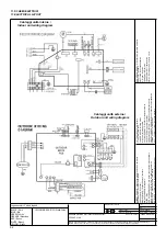
Страница 64: ...ANGE Arancione RED Rosso WHITE Bianco YELLOW Giallo Cablaggi unità esterna Outdoor unit wiring diagram A_COMP B_COMP Relay Relè COMP Compressor Compressore CAP1 Outdoor fan capacitor Condensatore ventilatore esterno CAP2 3 Outdoor compressor capacitor Condensatore compressore FAN Outdoor fan motor Ventilatore unità esterna MAIN BOARD Scheda di contollo principale RT1 2 A system low pressure thrott...

Страница 65: ...7 7 8 1 8 1 8 6 9 8 6 9 5 5 5 5 8 8 8 1 8 1 7 7 1 1 8 6 9 8 6 9 8 1 8 1 1 1 8 8 0 34 0 34 8 6 9 8 6 9 5 5 5 5 8 8 5 5 5 5 8 8 1 1 1 1 1 1 309 309 1 1 1 1 309 309 1 1 1 1 1 1 5 5 5 5 8 8 8 8 7 7 57 57 57 57 7 7 21 21 21 21 21 21 3 1 7 21 3 1 7 21 72 1 225 81 7 72 1 225 81 7 9 9 9 9 㨫㨵 㨫㨵 287 225 81 7 32 5 287 225 81 7 32 5 72 1 225 81 7 72 1 225 81 7 72 1 225 81 7 72 1 225 81 7 81 7 21 2 6 7 81 7 2...

Страница 66: ......

Отзывы: