4 - Module operations—Equalization
4–3
4.3 Equalization
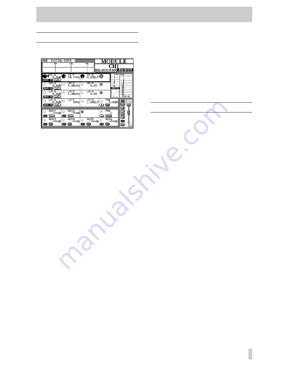
The first three PODs in the first four POD rows of the
MODULE
screen control the equalization.
As the equalization settings are changed, the graphi-
cal representation of the EQ response also changes.
The four EQ bands are named
HI
(high),
HM
(high-
mid),
LM
(low-mid) and
LO
(low). The
HI
and
LO
bands differ from the other two, as explained
below.
The gain of the bands is between
+15dB
and
-15 dB
in 62 steps.
However, the high and low bands can be set to act as
lowpass and highpass filters, respectively, by turning
the gain to below the minimum
-15dB
setting.
If the gain is turned below
-15dB
on the HM and
LM bands, they change to notch-type filters.
Each of the four EQ bands covers the same frequency
range:
32Hz
to
19kHz
, selectable over a 112-
step range using POD 2.
The Q of each band (the frequency range over which
it operates) can be set from 8.65 to 0.27 in 25 steps.
The high and low bands can be set to provide shelv-
ing EQ, as opposed to peaking-type EQ.
Each band can be turned on and off using the left
switch of POD 1.
The gain of each band can be flattened using the right
switch of POD 1.
In order to bypass the equalization circuit for the
module completely, the
EQ
key to the right of the
display screen should be pressed. When the EQ is
bypassed, the response curve at the top of the display
is “grayed out” to show that EQ settings have no
audible effect, but making adjustments using the
PODs will change the shape of the curve. When the
EQ is brought back, these changes will take effect.
When two channels have been linked into a stereo
pair, or when one of the two stereo inputs is selected,
the changes made to the equalization affect both
channels equally.
EQ settings, once made, may be stored in the EQ
library for further recall. The way in which this is
done is explained in the section of this manual deal-
ing with the TM-D4000 libraries (8, “Library func-
tions”).
4.4 Channel-to-buss assignments
There are two ways of assigning channels to the eight
output busses, the stereo busses, or for direct output:
using the dedicated
ASSIGN
key or from the
MODULE
screen.
4.4.1 Using the MODULE screen for buss
assignment
The status of the keys to the right of the display
screen are shown:
EQ
,
DYNAMICS
, the buss and ste-
reo assignment keys, and the direct out status (for
input channels 1 through 16).
The function of the
EQ
and
DYNAMICS
keys are
explained in the appropriate places (4.3, “Equaliza-
tion” and 4.6, “Dynamics processor settings”).
The channel can be assigned to any combination of
the eight output busses and the stereo output buss.
Busses are selected in pairs (1–2, 3–4, 5–6, 7–8).
As with most analog consoles when a buss pair is
selected, the odd-numbered buss of the pair corre-
sponds to a hard left pan, and the even-numbered
buss corresponds to a hard right pan. Anything in
between will balance the channel signal proportion-
ately between the two busses.
Input channels 1 through 16 (the integral analog
inputs and the inputs of slot 1) can also be assigned
as direct outs (
DIR
on this screen).
They are sent from the outputs which correspond to
the input channel number, plus 16. In other words,
input channel 1, when selected for direct out, is out-
put from channel 17 (the first output channel of slot
2), channel 9 is output from channel 25 (the first out-
put channel of slot 3), etc. If slots 2 and 3 are not fit-
ted with interface cards, the
DIRECT
key will have
no effect.


