3–1
3 - System setup
This section describes the operations that should be
carried out to affect the operation of the TM-D4000
as a whole.
These include:
• Digital I/O setup
• Word clock setup
• System options
It is important to understand the basic principles
explained here. If you do not, it will be more difficult
to achieve satisfactory results with your TM-D4000.
NOTE
The Cascade setup (accessed through the
DIGITAL I/O key) is described in 11, “Cas-
cade”, the Solo setup in 5, “Monitoring”, and
the Surround setup in 6, “Surround modes”.
3.1 I/O setup
1
With the
SHIFT
indicator off, press the
DIGITAL I/O
key
[5]
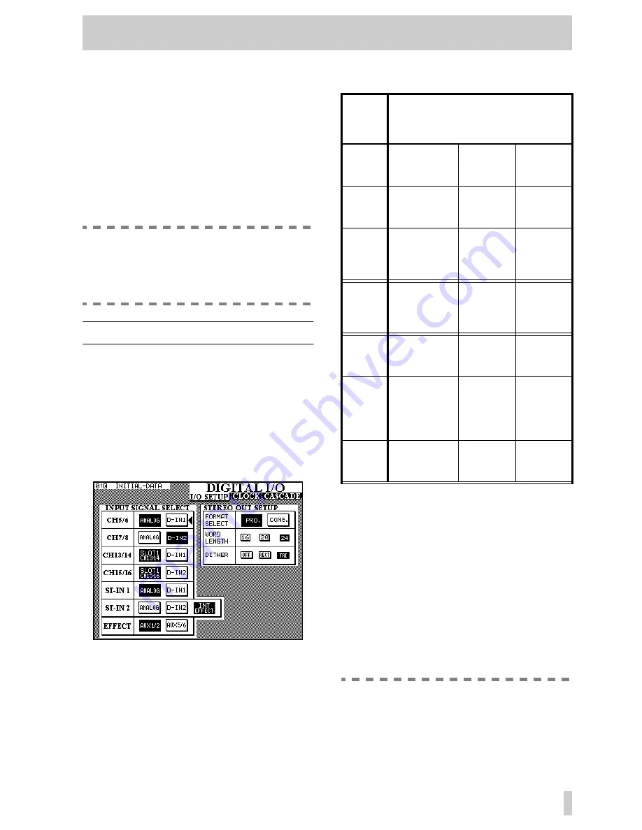
until the screen below
appears.
This screen allows the selection and assignment of
the digital inputs to channels. Note that the same dig-
ital input may appear as an input option for more
than one pair of channels. If a digital input is selected
as the source of more than one pair of channels, it
will appear at all these channels simultaneously.
The options available are:
3.1.1 STEREO OUT settings
In addition to these input sources, changes to param-
eters affecting the digital output of the
STEREO
OUT
can be made.
Firstly, the
STEREO OUT
can be selected as being in
either professional (
PRO.
) or consumer
(
CONS.
) format.
Changing the setting made here will also affect the
format of the output from any IF-AE4000 interface
cards fitted in the expansion slots.
NOTE
The Consumer format, when output from the
unbalanced RCA STEREO OUT jack, corre-
sponds to the IEC61958 (SPDIF) format.
Input
c
hannels
Available sources
5 & 6
Analog (integral
analog chan-
nels 5 and 6)
D-IN1 (XLR-
type)
—
7 & 8
Analog (integral
analog chan-
nels 7 and 8)
D-IN2 (RCA)
—
13 & 14
Slot 1 CH13-14
(channels 7 and
8 of the card in
slot 1)
D-IN1 (XLR-
type9
—
15 & 16
Slot 1 CH15–16)
channels 7 and
8 of the card in
slot 1)
D-IN2 (RCA)
—
ST-IN 1
ANALOG (inte-
gral stereo
inputs)
D-IN1 (XLR-
type)
—
ST-IN 2
ANALOG (inte-
gral stereo ana-
log inputs
D-IN2 (RCA)
INT
EFFECT
(internal
effect pro-
cessor)
EFFECT
a
a. The source of the internal effect processor
input
AUX1/2 (Aux
busses 1 and 2)
AUX5/6
(Aux bus-
ses 5 and 6)
—


