


2 - Principles of operation—Using the PODs
2–2
2.3 Using the PODs
A POD consists of a continuous rotary encoder or
“knob”, with two keys (or “switches”) under it. There
are four PODs located directly under the display
screen.
The knob is used to set continuously variable param-
eters shown on the screen (for example, the amount
of signal sent to an Aux buss), while the switches are
used for “on/off”-type screen parameters (e.g. pre-or
post-fader send).
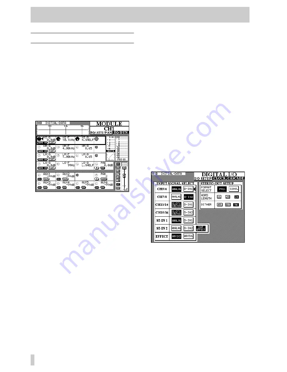
A typical screen showing POD use is shown below
(the method of actually selecting screens is given
below):
The controls on the screen are shown in rows, each
row corresponding to the four PODs.
The heavy blinking box surrounding a row shows the
currently-active row. Turning a POD knob will have
the effect of changing the corresponding parameter
in the active row (turning the left POD knob will
adjust the left parameter in the active row, etc.).
In the example above, the right on-screen control in
the active row is “grayed out”. This means that the
corresponding POD has no function when this row is
active.
Note that PODs which are enabled, but not in the cur-
rently active row, are shown as small dashed circles.
PODs which are disabled, and not in the currently
active row, are shown as small gray circles.
Where both switches of a POD are unused, they are
not displayed on screen. When only one switch of a
POD is used, the other is “grayed out”.
To change the active row, use the
ROW CURSOR
keys to the right of the PODs to move the heavy
blinking box indicating the active row.
In addition to the POD knobs, the POD switches can
also be used in a number of cases in this screen to set
various parameters.
In this way, comparatively few physical controls can
be made to adjust many parameters. Since these con-
trols are centralized, this allows for very efficient
working with the TM-D4000.
2.3.1 Selecting screens
Display screens are selected using the group of keys
to the left of the display screen.
Sometimes a key will have two labels, one above and
one below. The function described by the lower label
is accessed by pressing the
SHIFT
key so that the
SHIFT
indicator lights, and then pressing the appro-
priate key.
The screen shown below is a
DIGITAL I/O
screen, as shown by the title in the top right corner of
the screen. Accordingly, the (unshifted) key whose
upper label is
DIGITAL I/O
should be pressed.
Note that this screen contains three “tabs” under the
title. This is because there are more parameters
which fall under the heading of “digital I/O” than can
fit on one screen.
Currently, the
I/O SETUP
tab is at the top, and
it is these parameters which are available for editing.
To change to the next tab,
CLOCK
, press the
DIGITAL I/O
key once more (with the
SHIFT
indica-
tor lit).
Another press of the
DIGITAL I/O
key will bring the
CASCADE
tab to the front, and pressing it one


