background image

To trim thread

74

Chapter 5

QS07

2-2.  

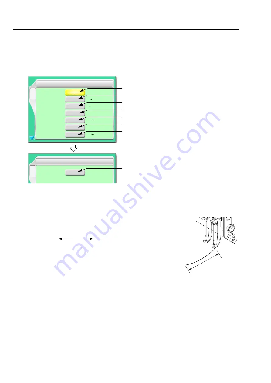
To trim thread automatically (ATH)

It is the setting to trim thread.

2-2-1.  

Explanation on the screen

[a] 

To trim thread automatically

YES: To trim

NO: Not to trim thread

[b] 

Length of remaining upper thread after thread trimming (1 in the 

right figure)

When upper thread remains on the fabric, select the value of "-".

If sewing is impossible due to short of remaining length of upper 

thread, select the value of "+".

When "N" is displayed, the value differs in each needle bar.

Regarding the setting of needle bar unit, refer to the detailed page.(p.101)

[c] 

Number of lowering the needle bar by slow operation at start after thread trimming or after data 

set

F2

YES

9 ATH

YES/NO

N

-8


4

2

Return Stitches

NO

1/2/T0/T1/T2/NO

Return Stitch Length

N

A

A/B/C/D

Thread Trim Length

9

+8

Tie Stitches

Tie Stitch Length

N

0.6 2.0 [mm]

0.2 2.0 [mm]

[b]

F2

9 ATH

B

A/B

Hook

Next page

[c]

[d]

[e]

[f]

[g]

[h]

[a]

To trim thread automatically

Remaining length of upper thread

Number of lowering needle bar at slow operation

Return Stitches

Return Stitch Length

Tie Stitches

Tie Stitch Length

Thread holder

Inching after ATH

1

-8

+8

Short

Long

0

Содержание TEMX-C Series

Страница 1: ...r 1 Turn ON the power 34 2 To pass thread to set fabric 37 3 To register a design in the memory of the machine 40 4 To decide a design to embroider and the color change order 48 5 To decide the design start position 55 6 Checking items before embroidering 62 7 Embroidery starts 66 ...

Страница 2: ...ECAUTIONS To prevent any harm or damage to the person who use this product or other person we describe items that must be surely followed as below Prohibited items Items that may cause electric shock if not observed Items that must be followed carefully to ensure safe operation Indicates that there is a lot of danger of death or serious injuries 1 if handled by mistake Indicates that there is a li...

Страница 3: ... each part 1 Name of each part 14 1 1 Single head machine 14 1 2 Multi head machine 15 2 How to use each part 16 2 1 Operation panel 16 2 2 Sleep mode key 20 2 3 Emergency stop switch 21 2 4 Needle Base LED Lamp 21 2 5 Main shaft handle Color change handle Single head machine only 22 2 6 To move Up Down the table Multi head machine only 23 2 7 Option and others 25 Chapter 3 Screen 1 Screen display...

Страница 4: ...olor change order Needle Bar Selection 51 4 3 To change color automatically to start operation automatically Auto Color Change AC Auto Start AS 53 5 To decide the design start position 55 5 1 To check the design size and the setting contents of the design Check of design 55 5 2 To lower the needle bar to adjust the frame position Needle bar operation 56 5 3 To move the frame to the design start po...

Страница 5: ... To stop the machine 86 4 1 To stop the machine automatically when reaching the set value Preset Halt 86 4 2 To stop the machine before needle bar hits the frame Software Frame Limit 87 4 3 To stop the machine with needle bar stuck in the material Stop at Lower D Point 89 4 4 To stop at Frame Limit Frame Limit setting 90 5 To change the direction and the size of the design 92 5 1 To perform enlarg...

Страница 6: ...1 To change password Functional limit of password 124 10 2 To cancel the password 126 11 Other functions that must be remembered 127 11 1 To check the number of total stitches up to now Total Stitch Counter 127 11 2 To color in every needle bar Needle Bar Color 128 11 3 To display the setting color when making the design Needle bar information 129 11 4 To check version of current software Software...

Страница 7: ...on automatically Auto Origin Return 152 5 To move the frame to the position registered 153 5 1 To move the frame automatically at the start and the end of embroidery Automatic Offset 153 5 2 To move the frame automatically at the start in the middle and the end of embroidery 155 5 3 To return the frame to the offset start position manually Return to the offset origin 156 Chapter 7 Function for sto...

Страница 8: ...in Device IV 187 3 Functions concerning optional device 190 3 1 To make the air compressor available for use Air Pressure Sensor 190 3 2 Lochrose counter 192 Chapter 9 Countermeasure when some trouble occurs in the machine 1 Countermeasure when the machine stopped 194 1 1 Normal stop 194 1 2 Abnormal stop 195 1 3 Stop due to malfunction 197 2 Trouble examples and Corrective actions 201 2 1 Thread ...

Страница 9: ...f input voltage Single head machine only 217 1 4 Machine weight 218 2 Function code 219 2 1 Function codes that can be edited by this machine 219 2 2 Function codes that cannot be edited by this machine display only 220 3 Electrical component 221 3 1 Layout of electrical component card 221 3 2 Electrical system diagram Single head machine 222 3 3 Electrical system diagram Multi head machine 223 4 ...

Страница 10: ... Color 128 1 Maximum RPM 62 2 Total Stitch Counter Design Timer 127 3 Frame Back Frame Forward 136 5 Frame Back All Head Sew 140 6 Preset Halt 86 7 Frame Type 141 10 Stop at Lower D point 89 1 Trace 60 2 Manual Color Change 72 3 Manual ATH 73 4 Return to the design start position 151 5 Manual Offset 145 6 Return to the offset origin 156 10 Needle bar operation 56 Single head machine Multi head mac...

Страница 11: ...ravel Speed 111 6 Thread Detection 77 9 ATH 74 10 Upper thread lock timing 106 Multi head machine only 1Boring 185 2 Sequin 187 Sequin Device IV 3 Cording 184 5 Zigzag Cording Device 181 7 Table Up Down 186 10 Lochrose embroidery device 182 1 Data Edit 114 Modification 1 Data edit 117 Insertion 1 Data Edit 121 Deleting 2 Cleanup 104 4 Move a design 161 5 Copy a design 162 6 Changing design name 16...

Страница 12: ... 124 3 Setting in units of Needle bar 101 6 Frame Limit Setting 90 7 Frame origin memory with the power ON 150 SET F2 1 Max Revolution Limit 85 2 Frame Start Timing 105 3 Frame Drive Adjustment 107 4 ATH Drive Start Timing 82 6 Return the frame after manual frame travel 146 8 Power resume 147 9 Frame origin memory 148 SET F3 2 Weak Brake 132 3 Air Pressure Sensor 190 7 Sequin device 178 10 Network...

Страница 13: ...To search from the menu key ...

Страница 14: ... 9 10 11 1 RR07 Chapter 1 Items that must be followed carefully 1 Safety Precautions 2 2 Important warning items for safe operation UL spec and CSA spec machines 6 3 Warning labels 9 4 Inspection before starting work 11 ...

Страница 15: ...s Especially it is dangerous around needle rotary hook take up lever pulley and speed reduction box This machine used strong magnet The person who is mounted with internal implantable medical electronics like a pacemaker should not use this machine The person who is mounted with an equipment described above also should not access to magnet inside of this machine This internal equipment could malfu...

Страница 16: ...ck Insert the power cable plug fully If a metallic part touches a blade in the plug it may cause fire and or electric shock Keep away electrical units from water and chemicals Entry or splashing of them into control units leads to short circuits causing fire electric shock and other troubles If water or other chemicals enter the unit shut off the power at the primary power source of the machine an...

Страница 17: ...tion and installation of breaker of leak current and leak current relay used for the factory are not correct malfunctioning of the machine may occur Regarding connection of power cord observe the following items Use a breaker of electric current leakage and leak current relay for which measures are taken against harmonics and surge If you use conventional breaker and relay without such measures se...

Страница 18: ...hreads do not become disheveled Humidity 30 to 95 RH relative humidity without condensation Ambient temperature 5 to 40 C during operation 10 to 60 C during storage Avoid direct sunlight If the machine is exposed to direct sunlight over an extended period of time the machine body may be discolored or deformed Put curtains or shades to the site to prevent the machine from direct sunlight Provide en...

Страница 19: ...urer as contained in this manual Never operate this appliance if it has a damaged cord or plug if it is not working properly if it has been dropped or damaged or dropped into water Please consult the nearest authorized dealer or service center and use this appliance after the examination repair electrical or mechanical adjustment has been made Never operate the appliance with any air openings bloc...

Страница 20: ...nnect turn all controls to the off O position then remove plug from outlet Do not unplug by pulling on cord To unplug grasp the plug not the cord Connect this appliance to a properly grounded outlet only See Grounding Instructions Improper connection of the equipment grounding conductor can result in a risk of electric shock The conductor with insulation having an outer surface that is green with ...

Страница 21: ...be connected to a permanent ground such as a properly grounded outlet box cover Whenever the adaptor is used it must be held in place by the metal screw If the product is used in a nominal rating more than 120V This product is for use on a circuit having a nominal rating more than 120V and is factory equipped with a specific electric cord and plug that looks like the plug illustrated in sketch D i...

Страница 22: ...detach the warning label nor make the printing surface illegible by paint etc If the warning label is missed or damaged contact your local distributor 3 1 Single head machine There could be danger of electric shock burning or death Persons except service personnel designated by Tajima should not open covers When you open the cover turn OFF the power switch and wait for four minutes A B D F230 High...

Страница 23: ...zas en movimiento mien tras la máquina esté en funcionamiento S011 There could be danger of electric shock burning or death Persons except service personnel designated by Tajima should not open covers When you open the cover turn OFF the power switch and wait for four minutes A B D E High voltage indication mark C Sticking positin A B C There could be danger of being caught or clipped Other person...

Страница 24: ...eedle Is needle bent Is direction of needle correct Is needle broken Rotary hook p 207 Is cleaning lubrication performed in adequate frequency Tension base switch p 64 Is the switch of head to use turned ON Is the switch of unused head turned OFF Needle bar suspension lever p 65 Is the lever of head to use set to ON Is the lever of unused head set to OFF Middle thread guide adjusting lever p 65 Is...

Страница 25: ...Inspection before starting work 12 Chapter 1 ...

Страница 26: ... E 1 2 3 4 5 6 7 8 9 10 11 13 PT10 Chapter 2 Name and the way to use of each part 1 Name of each part 14 2 How to use each part 16 ...

Страница 27: ...ngle head machine 1 3 4 5 6 7 8 2 9 10 11 1 Thread course 2 Operation panel p 16 3 Head p 64 4 Needle Base LED Lamp p 21 5 Emergency stop switch p 21 6 Stand option 7 Cylinder bed 8 Start stop switch p 66 9 Power switch p 34 10 Caster 11 Vibration preventive base ...

Страница 28: ... 2 Multi head machine 1 2 3 4 5 6 7 8 9 10 5 1 Y axis motor 2 Thread course 3 Operation panel p 16 4 X axis motor 5 Power switch p 34 6 Emergency stop switch p 21 7 Start stop switch p 66 8 Border frame 9 Head p 64 10 Cylinder bed 11 Table up down device p 23 11 ...

Страница 29: ...How to use each part 16 Chapter 2 PT10 2 How to use each part 2 1 Operation panel Front face Back face Side face USB port p 18 Various types of key operation p 17 USB port LAN port p 19 ...

Страница 30: ...rated as below in this manual It is illustrated as below in this manual 1 Sleep mode key p 20 Switch to power save mode To release press this key again 2 Condition of the machine AS Auto start To perform lit Not to perform unlit FB Frame back forward p 67 Frame back lit Frame forward unlit Main shaft stop position Fixed position lit normal Other than the fixed position unlit abnormal Lower dead po...

Страница 31: ... USB memory When installing the software in the machine Some type and or capacity of USB memory may not be used for this machine In this case please buy USB memory recommended by Tajima For details please consult the distributor About a use of USB memory observe the items to notice described below Do not turn ON the machine power in the state that the USB memory is connected to the operation panel...

Страница 32: ...When you insert the USB memory do not mistake the direction of connector The USB memory and its inside card could be damaged Do not insert the USB memory in the state that dirt or dust are attached to the inside of the connector Insert the USB memory slowly and gently Insert the USB memory upright against the port insert slot Oblique insertion could damage to inside card due to interference of con...

Страница 33: ...sleep mode key will be unlit Cancellation will be completed When the following message will be displayed after the cancellation press the SET key Pressing the SET key will move the frame When performing this operation do not put your hands etc on the machine table Moving frame could injure you AS FB Sleep mode key Frame origin memory YES SET This message will be displayed in single head machine on...

Страница 34: ... usual 2 4 Needle Base LED Lamp Needle Base LED Lamp is equipped to the single head machine Spec of the machine Condition after stop How to release EN spec European safety spec The power is turned OFF 1 Turn the switch clockwise The power will be turned ON 2 Start the operation Excluding EN spec and Japanese domestic use The machine will switch to the sleep mode 1 Turn the switch clockwise 2 Press...

Страница 35: ...dle at the position where the screw faces directly above odd numbered needle or directly below even numbered needle 2 5 2 Main shaft handle Turning this handle by hand will cause the needle bar to lower When turning this handle with the power ON follow the procedure below 1 Press F3 key while pressing SET key 2 Select 2 Weak brake and press Set key 3 Select NO in the below screen and press SET key...

Страница 36: ...cated by an arrow 5 To finish working adjust the main shaft angle in the screen to 100 6 Press E key 2 6 To move Up Down the table Multi head machine only The device will work only under the following conditions When the frame is positioned at the reamost When Table Up Down is set to YES p 186 Auto sub table lifter ...

Страница 37: ...the table to the uppermost fix the toggle clamp When performing this operation do not put your hands etc on the machine table Moving up down table could injure you Do not operate the machine under the following condition The frame or its surrounding parts could be broken In the state that the frame is equipped In the state that the rotary hook is opened In the state that the toggle clamp is fixed ...

Страница 38: ...nually Regarding how to use refer to the detail page p 59 2 7 2 Bar code reader Register a design in the memory of the machine by using the bar code reader Please buy a corresponding product to the USB port We do not sell it Regarding how to use refer to the detail page p 45 When not using put it in the pocket Pocket Connect it to the USB port back face p 19 Bar code ...

Страница 39: ...How to use each part 26 Chapter 2 ...

Страница 40: ... E 1 2 3 4 5 6 7 8 9 10 11 27 PT10 Chapter 3 Screen 1 Screen display 28 2 Message display 31 ...

Страница 41: ...offset p 153 Existence Absence 6 Needle bar No selected in every step p 51 7 Setting to return the frame to the front during embroidery p 155 With setting 8 Frame that is currently set 9 Software Frame Limit p 87 With setting 10 Current number of stitches 11 Current frame position mm 12 Maximum speed p 62 During stop Maximum speed will be displayed During operation The actual embroidery speed will...

Страница 42: ...5 Automatic Offset 6 A S after Auto Data Set 10 Needle Bar Color 1 1 Select YES NO by using the jog dial and press SET key To lower the cursor press SET key or To return the screen press the E key YES B AC YES NO AS YES NO YES NO Same Color AS NO NO NO 1 1 Auto Color Change AC Auto Start AS 1 File name up to 8 characters 2 To return the cursor to delete a character 3 To decide a character and a nu...

Страница 43: ... position Frame Back All Head Sew Frame Type 12 13 6 7 8 9 11 Upper T Detection Under T Detection Under T D Step Ratio Auto Color Change AC Automatic start AS A S after Auto Data Set Auto Origin Return Jump Convert Auto Jump Automatic thread trimming ATH Tail Length Return Stitches ATH Tie Stitches M shaft Inching after ATH 70 4 1 Design of which data is set to be embroidered from now 2 File name ...

Страница 44: ... the storing mode T3 T2 T of the design About T2 One design will be generated by three types of file indication TAJIMA_W CT0 TAJIMA_W DGF TAJIMA_W TBF Therefore please handle these three files as a set Storing mode Indication in a personal computer Application T3 TAJIMA_W TCF Data integrating CT0 DGF and TBF of T2 T2 TAJIMA_W CT0 Color change order design start point TAJIMA_W DGF Image data on a p...

Страница 45: ... 4 Repeat of design 5 Automatic offset The message shown left will be displayed only when the machine reads condition data at 2 1 This message is displayed when setting data of design Design start position means the frame position where this design was started embroidering last time OK to move a frame to the Start Point of Design Data X 115 7 Y 153 2 YES SET NO E These figures mean the place to mo...

Страница 46: ...the power 34 2 To pass thread to set fabric 37 3 To register a design in the memory of the machine 40 4 To decide a design to embroider and the color change order 48 5 To decide the design start position 55 6 Checking items before embroidering 62 7 Embroidery starts 66 ...

Страница 47: ...itch depending on the model 1 1 1 Single head machine 1 1 2 Multi head machine Do not turn ON the machine power in the state that the USB memory is connected to the operation panel except when installing the software in the machine The system sometimes may not start up ON OFF ON OFF CAUTION This type can be locked ...

Страница 48: ...locking ON T R I P P E D Handle Groove Lock plate Commercial 1 Turn the handle toward direction A to the position of the groove 2 Push the lock plate to the direction indicated by a big arrow and return the handle to the direction B the original position 3 Lock item ...

Страница 49: ...S Press DEL to set up Software version installed in the machine will be displayed Now System Loading 40 Windows CE net Microsoft TEMX C Press SET The frame will move and return to the original position TAJIMA_W 14117 0 Frame origin memory YES SET This operation is for grasp of the frame position correctly and it is displayed every time when the power is turned ON This message will be displayed onl...

Страница 50: ...o set fabric 37 1 2 3 4 5 6 7 8 9 10 11 Chapter 4 RR07 2 To pass thread to set fabric 2 1 To pass thread Thread correctly at tension part indicated by arrows Otherwise it affects finishing of sewing Threader accessory ...

Страница 51: ...read tension badly Return the adjusting lever to the original position after passing the thread Otherwise it would cause the thread breakage or affect the thread tension badly Upper thread lock Thread take up 1 2 3 4 How to use adjusting lever 1 To raise the lever 2 To pass the thread 3 Return the lever after threading The screw should face to the front Lever Screw Lever spring CAUTION ...

Страница 52: ...tly on the embroidery frame Fix the fabric in the state of full stretch so that no lines remain on the fabric A B Cap frame Tubular goods frame Regarding how to stretch the fabric and replace the embroidery frame refer to the separate manual FRAME REPLACEMENT Typical example Border frame Clip Use the clip as shown in the figure below The frame should be fixed at section A and B in the figure below...

Страница 53: ...stored in the USB memory The total amount of folders or designs which can be read in one layer directory is 255 designs at the maximum b Folder c Shank 4 Data Input USB A Cap frame Border frame T2 TCF T3 TBF T DST T DST Layer directory a Folder b Design c Folders and designs stored in the USB memory will be displayed The design except the one shown at left will be displayed depending on the storin...

Страница 54: ...n a USB memory in the memory of the machine 1 Set a USB memory 2 To open screen 3 Select a design The operation differs depending on a storing place for the design a Design in a folder 256MB USB Pay attention to the direction 4 Data Input USB Pressing SET will display the folder or the design of the second layer directory To return to the original layer directory press E key ...

Страница 55: ...rmation screen p 30 To return the original screen press E key G001 TCF TAJIMA_W 14117 Are you ready Read Condition Data If the storing mode of the design is T3 or T2 the following message will appear 1 Data Input Memory A Group1 Group2 Group3 Group5 Group4 TBF 4 After that proceed to To decide a design to embroider Data setting p 48 Condition data means the start position of the color change order...

Страница 56: ...tion For details please consult the distributor 3 2 1 Explanation on the screen 3 2 2 How to operate not to use the bar code reader The following is an example when registering a design stored in a personal computer into the memory of the machine 1 After connecting the LAN cable to the LAN port at the back of the operation panel start up DG ML by Pulse 2 Check if network setting is YES p 180 3 To ...

Страница 57: ... memory of the machine This design has become the state that it is possible to embroider Data set is completed After that proceed to To change color automatically to start operation automatically Auto Color Change AC Auto Start AS p 53 TBF 3 Are you ready Read Condition Data Condition data means the color change order ...

Страница 58: ...r code reader to the USB port of the operation panel p 19 4 To set to main screen 5 To read bar code Condition data color change order is also read automatically This design has become the state that it is possible to embroider Data set is completed After that proceed to To change color automatically to start operation automatically Auto Color Change AC Auto Start AS p 53 Please buy a commercial i...

Страница 59: ...he machine is started stopped c When the power is turned ON again There are following conditions for pre reading design a Pre reading is available in one design only b When reading the bar code plural times during operation the design read finally will be selected c When a design embroidering is interrupted during the operation and the data of the other design is set a pre reading design will be d...

Страница 60: ...eader Deal with the following procedure If the problem is not solved please consult the distributor Error code No BC1 Press E key Resetting error Design data transmission to Spooler Rereading of bar code A 5 Switch to data input LAN screen and select the design manually Press SET key Completion of data set To perform Not to perform Transmit design data to Spooler Rereading of bar code Success Fail...

Страница 61: ...tory b Folder Folder name can be changed p 166 c Design registered in the memory of the machine 1 Data Input Memory A Group1 Group2 Group3 Group5 Group4 4 c b a Layer directory Folder Design registered in the memory of the machine The capacity of the machine memory is 200 designs at the maximum up to 2 000 000 stitches Group1 First layer directory Second layer directory Design name up to 8 charact...

Страница 62: ...broider 1 To open screen 2 Select a design The operation differs depending on a storing place for the design a Design in a folder b Design on the screen 1 Data Input Memory Pressing SET will display the folder or the design of the second layer directory To return to the original layer directory press E key 3 Pressing i key will display the design confirmation screen p 30 To return the original scr...

Страница 63: ...o embroider When performing this operation do not put your hands etc on the machine table Moving frame could injure you Are you ready OK to move a frame to the Start Point of Design Data When the move of the frame is not desired Pressing SET will move the frame then data set will be completed CAUTION ...

Страница 64: ...nge code in the design data The first section is called step 1 and the next section is called step 2 Step display differs depending on with without setting of Auto Color Change AC c Offset mark The illustrated example shows that the frame moves to the front automatically after finishing of step 3 p 155 However to move the frame the setting of Automatic Offset is necessary p 153 2 Needle Bar Select...

Страница 65: ... No to use at the step 1 Set also other needle bar No in the same procedure 4 2 3 How to operate to insert the offset mark The following is an example when insert the offset mark between step 2 and step 3 1 To select the step to insert the offset mark 2 To insert the offset mark To delete the offset mark 2 Needle Bar Selection 1 4 2 9 3 1 The offset mark is inserted between step 2 and step 3 in th...

Страница 66: ...e the following settings b Setting to start operation automatically after color change YES to perform NO not to perform Selecting NO will disable the following settings c Setting to start operation automatically when the same needle bar No is selected at before and after steps YES to perform NO not to perform The below example shows that selecting NO will stop the operation after step 1 finishes W...

Страница 67: ...an example when setting to the following condition To perform automatic color change To perform automatic start Starts automatically at same color 1 To open screen 2 To perform automatic color change 3 To perform automatic start 4 Starts automatically at same color 1 Automatic color change Automatic start YES YES YES ...

Страница 68: ...ress i key Current position Stitch Counter Function Stitch Length Design Counter Step OFFSET Data conversion Rotation Reversion Repeat M Repeat 0 88 4 0 0 59 6 59 2 From Design 1 8 3 10 5 7 2 7 8 4 80 3 3 130 0 pp 0 0 G0041 W Tajima 14117st 80 100 0 0 0 0 0 Design to be embroidered Repeat of design Enlargement reduction reversion of design Size of design mm 88 4 59 6 59 2 Start position of design ...

Страница 69: ... How to operate The following is an example when lowering the needle bar 1 To open screen 2 To lower the needle bar When performing this operation do not put your hands etc near the needle Moving up down of the needle bar could injure you Up To raise the needle bar Down To lower the needle bar 10 Needle bar operation Up CAUTION 10 Needle bar operation Up When pressing the SET key needle bars of al...

Страница 70: ...n the screen TAJIMA_W 14117 0 Main screen The current frame position is displayed by the numerical value mm The frame position is based on the frame origin The code means the frame travel direction X Y 150 0 100 0 X X Y Y Relation between frame travel direction and code 1 If the frame moves to the rear the mark will be Y 2 If the frame moves to the front the mark will be Y 3 If the frame moves to ...

Страница 71: ...l Jog shuttle a Switch to main screen Press E key plural times to switch to the main screen b To decide the frame travel direction Press E key to decide frame travel direction When performing this operation do not put your hands etc on the machine table Moving frame could injure you CAUTION Speed switching key Rear Left Front Right When you want to change the frame travel speed press the speed swi...

Страница 72: ... jog shuttle high speed The frame will move 3 To use Jog remote controller some models only a Switch to main screen Press E key plural times to switch to the main screen b To move the frame to design start position Tilt the stick The frame will move Jog dial Jog shuttle Stick Frame travel speed will be changed by degree of leaning condition of the stick ...

Страница 73: ...o not put your hands etc on the machine table Moving frame could injure you 1 2 3 4 5 6 7 Start position of design The number in the left picture indicates the path of the frame After completion of trace embroidering from that position is possible When repeat is set The machine will trace the whole designs after tracing the first design When automatic offset is set The machine traces according to ...

Страница 74: ... will be displayed Press E key c After checking the size of the design move the frame to the design start position d Perform tracing again To interrupt trace follow the procedure below a Suspend the operation by the bar switch or the stop switch Code No 1C1 will be displayed While a code No 1C1 is displayed do not turn OFF the power b Press E key c After that follow the message described below Low...

Страница 75: ...Maximum speed 6 1 2 How to operate The following is an example when setting the maximum speed to 950 1 To open screen Stitch Length Embroidering speed Up to 4 0 mm Maximum speed A in the right figure 4 1 mm to 11 9 mm Automatic change B in the right figure 12 0 mm and more Low speed C in the right figure p 83 1000 Speed display column During stop The maximum speed is displayed During operation Act...

Страница 76: ... Select maximum speed Selection of the value exceeding Max Revolution Limit is not possible When changing the maximum speed during operation turn the jog dial jog shuttle 950 rpm While turning the dial the following display appears The number described in is the maximum speed 850 ...

Страница 77: ...uspend the head electrically The switch manipulation during operation of the machine is invalid Even if the switch manipulation is performed it will become effective after the machine stops Thread breakage indicator lamp Lit in green In the state of embroidery possible Unlit In a state of suspending embroidery needle bar will not move down Blinking in green 1 1 Multi head machine only Frame back s...

Страница 78: ... head mechanically 3 Middle thread guide adjusting lever Move the lever so that the screw faces to the front ON In the state of embroidery possible OFF In a state of suspending embroidery It is located at the left side of the head Switch Adjusting lever Screw If embroidery is performed under the following condition it could affect to thread breakage or thread tension badly ...

Страница 79: ...top the machine press the stop switch 3 To start slow operation keep on pressing the start switch Releasing it will become normal operation Before starting the machine pay enough attention to the surrounding safety Moving needle bar and or frame could injure you CAUTION Multi head machine Stop switch Start switch Start switch Stop switch Single head machine ...

Страница 80: ... 1 stitch or setting unit Explanation is given as follows Current setting condition Setting condition of frame back forward can be checked by the operation panel p 17 When switching frame back and frame forward refer to the detail page p 136 If the machine detects thread breakage frame back will be set temporarily 7 2 1 Frame back forward by stop switch When performing this operation do not put yo...

Страница 81: ...or blinks in green Lit in red upper thread is broken Blinking in red under thread is broken 2 Code No number indicating stop factor will be displayed on the operation panel 291 Upper thread is broken 293 Under thread is broken Thread breakage indicator lamp An example for multi head machine 291 1 Stop by detecting thread breakage Reset E Code No No of head with thread breakage Multi head machine o...

Страница 82: ... a result mend sewing will be performed at the position 2 without sewing due to thread breakage Head without thread breakage In case of multi head machine The machine restarts embroidery from the position 3 next to where frame back started This example is for the case All head sewing after frame back is set as 0 p 140 Threader accessory Position where frame back started position where the machine ...

Страница 83: ... to the original position 7 4 Completion of embroidery Destination to move of the frame differs depending on setting of the machine Setting for automatic offset With Without Tension base switch Thread breakage indicator lamp will change from green to red The frame will move to the offset start position Frame travel However when automatic origin return is set the frame will move to the design start...

Страница 84: ... embroidery speed 83 4 To stop the machine 86 5 To change the direction and the size of the design 92 6 To embroider the same design repeatedly 94 7 To adjust finishing of sewing 98 8 To increase embroidering efficiency 109 9 To edit design 114 10 Setting and resetting of password 124 11 Other functions that must be remembered 127 ...

Страница 85: ...example that the needle bar is changed color to the 5th needle 1 To open screen 2 To select needle bar No and execute color change When performing this operation do not put your hands etc around the needle bar case Moving needle bar case could injure you 1 Current needle bar No 2 Manual Color Change CAUTION 2 Manual Color Change 1 5 Pressing SET key will move the needle bar ...

Страница 86: ...ed 1 To open screen 2 To execute thread trimming When performing this operation do not put your hands etc near the needle Moving up down of the needle bar could injure you 3 Manual ATH To trim thread Under thread To trim under thread only Multi head machine only If turning the jog dial while pressing SET with indicated Under thread will be displayed CAUTION 3 Manual ATH Pressing SET key will move ...

Страница 87: ...value differs in each needle bar Regarding the setting of needle bar unit refer to the detailed page p 101 c Number of lowering the needle bar by slow operation at start after thread trimming or after data set F2 YES 9 ATH YES NO N 8 4 2 Return Stitches NO 1 2 T0 T1 T2 NO Return Stitch Length N A A B C D Thread Trim Length 9 8 Tie Stitches Tie Stitch Length N 0 6 2 0 mm 0 2 2 0 mm b F2 9 ATH B A B...

Страница 88: ...n the right figure A on the screen is fixed It is impossible to change Without Return Stitches Stitch at start of embroidering 0 Triangle 1 2 3 T0 One reciprocation 1 2 1 Triangle one reciproca tion 1 3 4 5 2 T1 Two reciprocations 1 2 3 4 2 Triangle two reciproca tions 1 3 4 5 2 6 7 T2 Not to perform tie stitching Thread trimming position A To perform tie stitching after lowering the needle twice ...

Страница 89: ... timing is set to 2 and the number of Inching after ATH is set to 3 1 To open screen 2 To trim thread automatically 3 To select thread trim length 4 To select number of inching times at start after thread trimming 9 ATH YES 2 When N is displayed changing N to a value will set the detecting sensitivity in all needle bars to same 3 ...

Страница 90: ...tinuously The relationship between the number of detecting times and sensitivity is shown as follows b Setting how many consecutive times of detection of under thread ratio are regarded thread breakage to stop the machine 0 Not to stop even if under thread is broken N To stop if under thread is broken the detecting sensitivity differs in each needle bar p 101 2 4 6 8 To stop if under thread is bro...

Страница 91: ...tionship between detecting ratio and sensitivity is shown as follows 2 3 2 How to operate The following is an example that the number of upper thread breakage detecting times is set to 2 and the number of under thread breakage detecting times unit is set to 6 1 To open screen 2 To select number of upper thread breakage detecting times 3 To select number of under thread breakage detecting times uni...

Страница 92: ...rame at next stitch 2 4 1 Explanation on the screen 2 4 2 How to operate The following is an example that the number of consecutive jump code is set to 4 1 To open screen 2 To select number of consecutive jump codes 1 Jump Convert F1 3 NO 1 9 Frame Travel A Number of consecutive jump codes NO Not effected 1 to 9 Number of consecutive jump codes How to move frame to next stitch A Batch B As data Ju...

Страница 93: ...2 5 2 How to operate The following is an example that thread trimming code is added to 20th stitch 1 To open screen 2 To select a design The original design will be overwritten after editing Back up design data according to need 1Data edit Delete 1 2 3 4 5 6 7 8 9 10 0 0 Jump 8 4 Stitch 8 3 Stitch 11 5 Stitch 8 8 Stitch 1 13 Stitch 11 2 Stitch 12 3 Stitch 11 7 Stitch 25 15 Stitch Modify Insert Sti...

Страница 94: ...10 11 Chapter 5 PT10 3 To select stitch No to perform thread trimming 4 To select Insert and decide 5 To select Modify to move the cursor 6 To select ATH 7 To decide 20 12 0 Stitch 20th stitch Insert Are you ready Modify ATH Are you ready ...

Страница 95: ...iming is set to 5 1 To set to main screen 2 To press F2 key while pressing SET 3 To press F2 key 4 To select ATH drive start timing This machine was shipped after being set to optimum values To change these values consult the distributor Some operating condition could cause occurrence of fault in thread trimming 0 Timing to start moving thread trimming knife Value is of main shaft angle 4 ATH Driv...

Страница 96: ... speed by stitch length Min Revolution 3 1 1 Explanation on the screen 3 1 2 How to operate The following is an example that Low Speed R p 1M is set to 550 rpm 1 To open screen 2 To select Low speed R p 1M 600 rpm Maximum speed at stitch of which stitch length is 12 mm or more 1 Min Revolution 1 Min Revolution 600 rpm 550 rpm ...

Страница 97: ... Explanation on the screen 3 2 2 How to operate The following is an example that the maximum speed of the section surrounded by the function codes Low_S to Low_E is set to 700 1 To open screen 2 Select maximum speed Function name Function code Low Speed Start Stitch Low_S Low Speed End Stitch Low_E 2 Revolution Limit F2 500 Low speed code rpm Maximum speed of section surrounded by function codes L...

Страница 98: ...n 3 3 2 How to operate The following is an example that Max Revolution Limit is set to 950 1 To set to main screen 2 To press F2 key while pressing SET and press SET further 3 To cancel the password Regarding canceling method refer to the detail page p 126 4 To select limit of max revolution 1 Max Revolution Limit 1000 rpm Set F2 Upper limit value 1 Max Revolution Limit 950 ...

Страница 99: ...op Since embroidery is not finished it is possible to perform frame back NO Not to stop f Quantity of beads attached to Lochrose embroidery device option at left When the equipped beads run out the machine stops display of 1D5 To disable this function select NO This setting will be displayed when Lochrose embroidery device is set as L or L R p 182 g Quantity of beads attached to Lochrose embroider...

Страница 100: ...he machine before needle bar hits the frame Software Frame Limit 4 2 1 Explanation on the screen 6 Preset Halt 15000 6 Software Frame Limit F1 YES NO NO P1X mm Previous 0 Tubular Frame Limit 0 Frame Type Y mm 0 0 P2X mm 0 0 Y mm 0 0 Software Frame Limit YES To set NO Not to set Frame Type selected now It is impossible to change Software Frame Limit is memorized in every frame type Frame coordinate...

Страница 101: ...n screen 2 To make software frame limit effective 3 To decide P1 Point 1 4 To decide P2 Point 2 When performing this operation do not put your hands etc on the machine table Moving frame could injure you CAUTION 6 Software Frame Limit YES 150 85 The frame will move Frame coordinates P1 Point 1 150 320 The frame will move P2 Embroidery space Point 2 ...

Страница 102: ...his setting stop the machine with needle stuck in the material at the end of embroidery 4 3 1 Explanation on the screen 4 3 2 How to operate The following is an example that Stop at Lower D Point is set 1 To open screen 2 To set Stop at Lower D Point NO YES To set NO Not to set usual setting 10 Stop at Lower D point 10 Stop at Lower D Point NO YES ...

Страница 103: ...n a Stop at Frame Limit YES To stop usual setting NO Not to stop Selecting NO will not display the following message at data input 4 4 2 How to operate The following is an example that the frame is stopped at Frame Limit 1 To set to main screen 2 To press F1 key while pressing SET 3 To press F1 key Selecting NO will not stop the frame at frame limit The frame could interfere with the peripheral pa...

Страница 104: ...To stop the machine 91 1 2 3 4 5 6 7 8 9 10 11 Chapter 5 PT10 4 To make Frame Limit Setting effective YES ...

Страница 105: ... So when you embroider this design next time setting again will be unnecessary 5 1 1 Explanation on the screen a Crosswise X scale ratio b Lengthwise Y scale ratio c Rotating angle d Reversion 3 Data Conversion B a b c d Scale up down in crosswise Scale up down in lengthwise Rotation Reversion Y X Original size After enlargement The illustration shows an example of the same scale ratio in X Y Star...

Страница 106: ...4 5 6 7 8 9 10 11 Chapter 5 PT10 5 1 2 How to operate The following is an example that crosswise scale ratio and lengthwise scale ratio are set to 120 1 To open screen 2 To select crosswise scale ratio 3 To select lengthwise scale ratio 3 Data Conversion 120 120 ...

Страница 107: ...The illustration below is an example that the priority embroidery direction is lengthwise b Number of repeats in crosswise c Interval in crosswise mm Trim B 4 Repeat a b c d e f g Repeat pattern Number of repeats in crosswise Design interval Number of repeats in lengthwise Design interval Priority embroidering direction Thread trimming Display only c e 1 2 3 4 5 In case of pp c e 1 3 5 2 4 In case...

Страница 108: ...t be changed 6 1 2 How to operate The following is an example that repeat pattern pb the number of repeats in crosswise 3 interval in crosswise 60 the number of repeats in lengthwise 2 interval in lengthwise 50 priority direction X are set 1 To open screen 2 To select repeat pattern 3 To select number of repeats in crosswise When performing this operation do not put your hands etc on the machine t...

Страница 109: ...thwise 6 To select interval in lengthwise mm 7 To select priority embroidering direction To cancel the setting of repeat set the number of repeats in crosswise and the number of repeats in lengthwise to 1 60 The frame will move 2 50 The frame will move X After that switching the screen will return the frame to the original position ...

Страница 110: ...hen Auto Start AS is set to YES p 53 6 2 1 Explanation on the screen 6 2 2 How to operate The following is an example that Automatic Start after Automatic Data Set is set 1 To open screen 2 To set automatic start after automatic data set After embroidery is finished do not put your hands etc on the table Automatic start operation could injure you NO YES To set NO Not to set usual setting 6 Automat...

Страница 111: ... lengthwise a 4 Backlash F1 0 0 0 0 X 0 5 0 5 mm Y 0 5 0 5 mm b Correcting value in crosswise Correcting value in lengthwise 0 5mm Original stitch Stitch after correction 0 5 mm Stitch after correction Original stitch 0 5mm Original stitch Stitch after correction 0 5 mm Stitch after correction Original stitch Example of combination of X Y correcting value 0 5 mm 0 5 mm Stitch after correction Orig...

Страница 112: ...ength of satin stitch Satin Stitch 7 2 1 Explanation on the screen a Whole All satin stitches in the design are targets Part Satin stitches of the section surrounded by satin stitch codes Satin_S to Satin_E are targets b 1 2 of the value will be added to both sides of stitch length 4 Backlash 0 3 3 Satin Stitch F1 Whole Expansion 0 0 Range Whole Part 1 0 1 0 mm b a Applicable range Adding amount B...

Страница 113: ...al to be embroidered However dividing by jump will reduce embroidering efficiency 7 3 1 Explanation on the screen 3 Satin Stitch Part 0 4 2 Auto Jump F1 4 0 240 240 360 NO 2 0 mm 9 9 NO YES NO Frame Drive Keep up R p 1M Setting for auto jump NO Not to perform 2 0 to 9 9 The machine will jump automatically when a stitch exceeding a set value is given When a value is 4 0 the machine will jump automa...

Страница 114: ...t 3 Setting in units of Needle bar F1 Needle No Revolution Limit Thread Detection Automatic Thread Trimming ATH 900 rpm Upper thread 2 0 1 2 3 4 Under Unit 4 0 2 4 6 8 Under Step Ratio 80 30 100 3 8 8 Return Stitch Length 0 8 0 6 2 0 mm b c d e f g a 3 Setting in units of Needle bar 0 2 mm 2 0 h Set F1 Tie Stitch Length 0 6 Needle No Next page Needle bar No Number of upper thread breakage detectin...

Страница 115: ...ken 2 4 6 8 To stop if under thread is broken When selecting 4 the thread breakage will be detected after upper thread breaks four times continuously The relationship between the number of detecting times and sensitivity is shown as follows e Set sensitivity of d Change this value according to the type of fabric and thread to use This enables to prevent mis detection 30 to 100 To stop if under thr...

Страница 116: ... 3 the maximum speed is set to 950 and upper thread breakage detecting sensitivity is set to 3 1 To set to main screen 2 To press F1 key while pressing SET 3 To press F1 key 4 To select needle bar No 5 Select maximum speed 6 To select number of upper thread breakage detecting times SET F1 screen will be displayed 3 Setting in Units of Needle bar 3 950 3 ...

Страница 117: ...tion has an effect to decrease thread breakages 7 5 1 Explanation on the screen 7 5 2 How to operate The following is an example that the stitch length to remove is set to 0 5 1 To open screen 2 To select a design The original design will be overwritten after removing fine stitches Back up design data according to need 0 4 0 4 2 Cleanup 0 9 mm Indicated value or less stitches will be removed CAUTI...

Страница 118: ...e Drive Start Timing is set to 270 1 To set to main screen 2 To press F2 key while pressing SET To change this value consult the distributor Some operating condition could cause occurrence of fault in thread trimming and affect sewing 0 5 24 Target number of stitches will be displayed Are you ready 280 Timing to start moving the frame Value is of main shaft angle 230 Thread tension Weak 280 Strong...

Страница 119: ...g When upper thread is still highly visible at A set B or C b Timing to close upper thread lock Perform adjustment when upper thread remains on the fabric after thread trimming When upper thread is still highly visible set to B or C 2 Frame Drive Start Timing 280 270 F2 A 10 Upper thread lock timing A B C A Release Lock A B C a b Remaining length of upper thread Remaining length of upper thread af...

Страница 120: ...nds to be increased in value and decreased in value in general due to characteristic of the machine However this aptitude may not be applicable depending on setting condition of other items and or machine condition 10 Upper Thread Lock Timing B 0 3 Frame Drive Adjustment Frame Type Tubular X 4mm 12mm Y 4mm 12mm 0 0 0 3 3 3 3 3 3 3 3 Set F2 a Frame Type selected now p 141 The following values can b...

Страница 121: ...owing is an example that the stitch in crosswise direction of around 4 mm is set to 1 1 To set to main screen 2 To press F2 key while pressing SET 3 To press F2 key 4 To select stitch in crosswise direction of around 4 mm SET F2 screen will be displayed 3 Frame Drive Adjustment 1 ...

Страница 122: ...reen 8 1 2 Explanation for operation The following is an example that the number of Start Inching is set to 3 1 To open screen 2 To select number of lowering needle bar at slow operation 8 2 To collect up frame moving amount of consecutive jump stitches in a batch to feed the frame all at once Jump code combination This function corresponds to the multi head machine only It reduces the number of s...

Страница 123: ...hine only When sequin device III is equipped the machine does not have this function 8 3 1 Explanation on the screen 8 3 2 How to operate The following is an example that Color Change Speed is set to High 1 Press the F5 key within 10 seconds after turning ON the power and keep on pressing the key If the version of the software is displayed release the key 2 To select color change speed 5 Jump Code...

Страница 124: ...argets at origin return of the frame and or offset travel 8 4 1 Explanation on the screen 8 4 2 Explanation for operation The following is an example that Frame Travel Speed is set to to100 mm sec 1 To open screen 2 To select Frame Travel speed 200 mm sec 200 200 mm second 100 100 mm second 5 Frame Travel Speed 5 Frame Travel Speed 200 mm sec 100 mm sec ...

Страница 125: ... finishing embroidery YES To perform NO Not to perform 8 5 2 Explanation for operation The following is the example of Not to perform Automatic Data Set of the design and Delete the design automatically after finishing embroidery 1 Set to the main screen 2 Press A key while pressing SET key 3 Press A key 0 9 Auto Data Set after finishing embroidery Delete Data 0 YES NO SET A a b Perform Automatic ...

Страница 126: ...To increase embroidering efficiency 113 1 2 3 4 5 6 7 8 9 10 11 Chapter 5 QS07 4 Select NO Not to perform Automatic Data Set of the design 5 Select YES Delete the design automatically NO YES ...

Страница 127: ... 0 Y 0 0 jump code 1 To open screen 2 To select a design The original design will be overwritten after editing Back up design data according to need 1 Data Edit Delete 1 2 3 4 5 6 7 8 9 10 0 0 Jump 8 4 Stitch 8 3 Stitch 11 5 Stitch 8 8 Stitch 1 13 Stitch 11 2 Stitch 12 3 Stitch 11 7 Stitch 25 15 Stitch Modify Insert Stitch No X data Data to move the frame in crosswise When a value is 8 the frame t...

Страница 128: ...elect stitch No by using search function refer to the detail page p 116 b To select the stitch No by the jog dial jog shuttle follow the explanation below To select stitch No by the jog dial jog shuttle 3 To select stitch No to change 4 To select Modify 5 To edit X data 6 To edit Y data 7 To modify the function code 20 12 0 Stitch 20th stitch Modify 0 0 Jump ...

Страница 129: ...effective 4 To search stitch by function code 5 To complete to search and select Modify 6 To edit X data Are you ready Stitch Color Pressing SET key will search the stitch of Color by function code Pressing SET key further will search the next stitch When there is no selected function code display will not change Modify 0 PT10 ...

Страница 130: ...ll be displaced hereafter 9 2 1 Explanation on the screen 0 Jump Are you ready 1 Data edit Delete 1 2 3 4 5 6 7 8 9 10 0 0 Jump 8 4 Stitch 8 3 Stitch 11 5 Stitch 8 8 Stitch 1 13 Stitch 11 2 Stitch 12 3 Stitch 11 7 Stitch 25 15 Stitch Modify Insert Stitch No X data Data to move the frame in crosswise When a value is 8 the frame travel amount is 0 8 mm Y data Data to move the frame in lengthwise Whe...

Страница 131: ...g two types of selecting patterns a To select stitch No by using search function refer to the detail page p 120 b To select the stitch No by the jog dial jog shuttle follow the explanation below To select stitch No by the jog dial jog shuttle 3 To select stitch No to insert 4 To select Insert The original design will be overwritten after editing Back up design data according to need CAUTION 1 Data...

Страница 132: ...To edit design 119 1 2 3 4 5 6 7 8 9 10 11 Chapter 5 PT10 5 To execute insertion 6 To select Modify to move the cursor 7 To select Jump 8 To decide insertion Are you ready Modify Jump Are you ready ...

Страница 133: ...unction code 5 To complete to search and select Insert 6 To execute insertion 7 To select Modify to move the cursor Stitch Color Pressing SET key will search the stitch of Color by function code Pressing SET key further will search the next stitch When there is no selected function code display will not change Insert Are you ready Modify ...

Страница 134: ...hereafter 9 3 1 Explanation on the screen Jump Are you ready 1 Data Edit Delete 1 2 3 4 5 6 7 8 9 10 0 0 Jump 8 4 Stitch 8 3 Stitch 11 5 Stitch 8 8 Stitch 1 13 Stitch 11 2 Stitch 12 3 Stitch 11 7 Stitch 25 15 Stitch Modify Insert Stitch No X data Data to move the frame in crosswise When a value is 8 the frame travel amount is 0 8 mm Y data Data to move the frame in lengthwise When a value is 4 the...

Страница 135: ...selecting patterns a To select stitch No by using search function refer to the detail page p 123 b To select the stitch No by the jog dial jog shuttle follow the explanation below To select stitch No by the jog dial jog shuttle 3 To select stitch No to delete 4 To select Delete The original design will be overwritten after editing Back up design data according to need CAUTION 1 Data Edit 3 20 12 0...

Страница 136: ...e search function effective 4 To search stitch by function code 5 To select Delete 6 To decide deletion Are you ready Stitch Color Pressing SET key will search the stitch of Color by function code Pressing SET key further will search the next stitch When there is no selected function code display will not change Delete Are you ready ...

Страница 137: ...ing Manual 10 1 1 Explanation on the screen 10 1 2 How to operate The following is an example that the password is changed from 0000 to ZY98 1 To set to main screen 2 To press F1 key while pressing SET Set 1 Password Functional Limit F1 Password To return the cursor to delete a character To decide a character and a numeric Inputting column of current password Set 1 Password Functional Limit F1 New...

Страница 138: ...pter 5 PT10 3 To input current password a To input 0 b To input remaining password 0 0 0 in the same procedure c To decide 4 To input password after change a To input Z b To input Y c To input remaining password 9 8 in the same procedure d To decide 0 Enter Z Y Enter ...

Страница 139: ...procedure after canceling the password 10 2 1 Explanation on the screen 10 2 2 How to operate The following is an example that the password 0000 is cancelled 1 To input password 0 2 To input remaining password 0 0 0 in the same procedure 3 To decide Enter Set 1 Max Revolution Limit F2 Password To return the cursor to delete a character To decide a character and a numeric Inputting column of curren...

Страница 140: ...displayed check the total stitch counter 2 Total Stitch Counter Design Timer C 8752195 0 50 8 st H M S The number of total stitches embroidered up to now When resetting the value select 0 and press SET key Time elapsed from start after data set to the present The screen shows an example of 50 minutes and 8 seconds Counting continues even during sleep mode and turning OFF the power Embroidery time ...

Страница 141: ...lanation on the screen 11 2 2 How to operate The following is an example that the needle bar No 1 set to red 1 To open screen 2 To select needle bar No 3 To select color 4 To decide 10 Needle Bar Color B a b c d Pallet 32 colors Cursor selecting color Needle bar No Color to needle bar 10 Needle Bar Color 1 Are you ready ...

Страница 142: ...etting color when making the design 1 Set to the main screen 2 Press B key while pressing SET key 3 Press B key 4 Select YES Display the setting color when making the design When the information about the setting color is not included in the design data the setting of B 10 needle bar color will be effective 10 Needle bar information NO YES Display the color being set in B 10 needle bar color p 128...

Страница 143: ... 2 To press F4 key while pressing SET 11 5 To switch display language Language 11 5 1 Explanation on the screen Set F4 2 Date and Time 3 Machine Type 4 Machine Number 5 Machine Information 10 Language Ver Current software version 8 Software Version Since SET F4 screen will be displayed check the version of the software Set F4 2 Date and Time 3 Machine Type 4 Machine Number 5 Machine Information 8 ...

Страница 144: ...pter 5 PT10 11 5 2 Explanation for operation The following is an example that the language is changed to English 1 To set to main screen 2 To press F4 key while pressing SET 3 To press F4 key 4 To select language SET F4 screen will be displayed Spanish 10 Language English ...

Страница 145: ...to YES after starting the machine Always NO Not to fix the main shaft motor always while the main shaft stops Always NO will be displayed in single head machine only b Current main shaft angle When you desire to check the main shaft angle set the value of above a to NO or Always NO and then turn the main shaft When left code is displayed follow the procedure below 1 2 3 F3 2 Weak Brake Set YES 100...

Страница 146: ... 11 Chapter 5 PT10 11 6 2 How to operate The following is an example that the main shaft motor is set to not to fix 1 To set to main screen 2 To press F3 key while pressing SET 3 To press F3 key 4 To select Not to fix SET F3 screen will be displayed 2 Weak Brake NO ...

Страница 147: ...Other functions that must be remembered 134 Chapter 5 ...

Страница 148: ...ent 1 To return the frame Frame Back to advance the frame Frame Forward 136 2 Necessary works after replacing the frame 141 3 To return the frame to the original position 145 4 To return the frame to the design start position 151 5 To move the frame to the position registered 153 ...

Страница 149: ... example of setting frame forward 1 To open screen 2 To select FF Frame Forward 3 Frame Back Frame Forward c FB NO 1 39628 FB FF Color change unit Stitches FB FF Stitch Unit Stitch Counter 1 3 5 Switching of FB Frame Back FF Frame Forward To execute by color change unit p 137 To specify the number of stitches and execute p 137 To change the frame feed amount p 139 Current number of stitches It is ...

Страница 150: ... to perform 1 to end stitch To perform to perform frame back or frame forward by the number of stitches 1 2 2 How to operate The following is an example of executing frame forward by color change unit 1 To open screen 2 To select FF Frame Forward When performing this operation do not put your hands etc on the machine table Moving frame could injure you 3 Frame Back Frame Forward c FB NO 1 39628 FB...

Страница 151: ...ying the number of stitches and executing frame forward 1 To open screen 2 To select FF Frame Forward 3 To move the cursor to Specification by the number of stitches 4 To input the number of stitches and execute When performing this operation do not put your hands etc on the machine table Moving frame could injure you Pressing SET key will move the frame CAUTION 3 Frame Back Frame Forward FF 628 P...

Страница 152: ...e stop switch or the bar switch 1 3 1 Explanation on the screen 1 3 2 How to operate The following is an example of setting the frame feed amount to 5 1 To open screen 2 To move the cursor to FB FF feed unit 3 To select frame feed amount 3 Frame Back Frame Forward c FB NO 1 39628 FB FF Color change unit Stitches FB FF Stitch Unit Stitch Counter 1 3 5 Frame feed amount 1 Feed the frame by 1 stitch ...

Страница 153: ...wing Start Point to 3 and setting to Stop at the position just before All Head Sewing Start Point 1 To open screen 2 To select All Head Sewing Start Point 3 The machine stops at the position just before All Head Sewing Start Point 5 Frame Back All Head Sew c 4 ALL 0 9 st Halt Frame Back NO YES NO All heads sew the whole section of Frame Back When ALL is selected Halt before F B is fixed to NO ALL ...

Страница 154: ...mode according to the frame that is equipped Frame Type 2 1 1 Explanation on the screen c Frame Type 7 Frame Type Tubular Select the frame in the figure below In case of pocket frame select Cap Tubular Cap Border Cylindrical A Clamp T A Clamp B X EXT Single head machine only The following frame types will be displayed in the single head machine only ...

Страница 155: ...p 1 To open screen 2 To select the frame 3 To execute Frame Origin Memory The below message will not be displayed for the multi head machine The following message will be displayed only when Frame origin memory with the power ON is set to YES p 149 7 Frame Type Cap Pressing SET key will move the frame Frame origin memory YES SET is executed ...

Страница 156: ...on and it might cause the damage of the parts Center of the embroidery space Upper right position If the SET key is pressed the frame will move Press STOP switch immediately after moving the frame Frame origin memory YES SET Code No 5C1 will appear Move the frame to the upper right position from the center of embroidery space by manual frame travel Perform operation of Frame Origin Memory SET F2 P...

Страница 157: ...he design to set data conversion 2 2 1 Explanation on the screen 2 2 2 How to operate The following is an example of setting of design rotation by 180 to To perform 1 To set to main screen 2 To press B key while pressing SET 3 To make the design rotation by 180 on Cap Frame effective NO 1 Design rotation by 180 on Cap Frame Rotation of a design by 180 YES To set NO Not to set State of design rotat...

Страница 158: ...d manually after stopping the machine in the middle of embroidery 3 1 1 Explanation on the screen 3 1 2 How to operate The following is an example of executing manual offset 1 To open screen 2 To perform manual offset When performing this operation do not put your hands etc on the machine table Moving frame could injure you 5 Manual Offset To return the frame to the original position To execute No...

Страница 159: ...ch YES The frame will return to the original position and the machine will start operation NO The frame will not return The operation will start from the position after frame travel 3 2 2 How to operate The following is an example of returning the frame to the original position and starting the operation 1 To set to main screen 2 To press F2 key while pressing SET 3 To press F2 key 4 To return the...

Страница 160: ...ion on the screen 3 3 2 How to operate The following is an example of executing Power resume 1 To set to main screen 2 To press F2 key while pressing SET 3 To press F2 key When performing this operation do not put your hands etc near the needle or on the machine table Moving needle bar or frame could injure you SET 8 Power resume F2 ATH To return the frame to several stitches before the position w...

Страница 161: ...power OFF or during sleep mode in such a case as changing frame 2 After installation of software 3 When frame driver is changed When a frame origin is wrong the following troubles will occur Frame coordinates are not displayed correctly The frame does not return to the interrupted position even after performing power restoration Position of frame limit gets out of alignment only for single head ma...

Страница 162: ...the setting to display the message and execute Frame origin memory in the following conditions This function applies to the single head machine only 1 When the power is turned ON 2 When releasing sleep mode 3 When Frame type is changed When the embroidery is on the way or the main shaft is out of the fixed position the message will not be displayed When performing this operation do not put your ha...

Страница 163: ... the message to urge frame origin memory when the power is turned ON 1 To set to main screen 2 To press F1 key while pressing SET 3 To press F1 key 4 To display the message NO 7 Frame origin memory with the power ON Display of the message to urge Frame Origin Memory YES To display NO Not to display SET F1 screen will be displayed 7 Frame origin memory ON YES ...

Страница 164: ...he machine 4 1 1 Explanation on the screen 4 1 2 How to operate The following is an example of executing design start position return 1 To open screen 2 To execute design start position return When performing this operation do not put your hands etc on the machine table Moving frame could injure you 4 Return to the design start position To return the frame to the design start position Not to execu...

Страница 165: ...When automatic offset is set the frame will return to an offset start position p 153 4 2 1 Explanation on the screen 4 2 2 How to operate The following is an example of setting Automatic origin return 1 To open screen 2 To make Auto origin return effective After embroidery is finished do not put your hands etc on the table Moving frame could injure you NO 4 Automatic Origin Return Auto Origin Retu...

Страница 166: ...from the offset start position A through the offset middle position B and move to the design start position C then the embroidery will start 2 When embroidery is finished the frame will pass from the design end point D through the offset middle position B and return to the offset start position A 5 1 1 Explanation on the screen a Offset middle position B The position where the frame will pass This...

Страница 167: ...e OF2 Offset Start position A To cancel the setting for automatic offset set the values of OF1 and OP2 described above to 0 When performing this operation do not put your hands etc on the machine table Moving frame could injure you At the start and the end of embroidery do not put your hands etc on the table Moving frame could injure you CAUTION 5 Automatic Offset The current frame position will b...

Страница 168: ...ter then the embroidery will start 2 During embroidery the frame will pass from the color change point D through the offset middle position B and return to the offset start position A After performing works for applique here the frame will pass through the offset middle position B move to the color change point D then start embroidery by switch operation 3 When embroidery is finished the frame wil...

Страница 169: ...rn the frame to the offset start position manually Return to the offset origin This function makes the frame return to the offset start position in the middle of emboridery when you stopped the machine It it possible to operate only when automatic offset is set The offset middle position is not passed 5 3 1 Explanation on the screen 2 Needle Bar Selection 2 9 3 1 2 9 3 1 Blinking 2 9 3 1 Blinking ...

Страница 170: ...example of executing offset return 1 To open screen 2 To execute offset return When performing this operation do not put your hands etc on the machine table Moving frame could injure you CAUTION 6 Return to the offset origin Pressing SET will move the frame To return to the original position perform Manual offset p 145 QS07 ...

Страница 171: ...To move the frame to the position registered 158 Chapter 6 ...

Страница 172: ... E 1 2 3 4 5 6 7 8 9 10 11 159 PT10 Chapter 7 Function for storing and deleting of design 1 Design stored in the memory of the machine 160 2 Design stored in USB memory 172 ...

Страница 173: ...1 1 Explanation on the screen 1 1 2 How to operate The following is an example of deleting a selected design 1 To open screen 2 Select a deleting method 3 To select and decide a design 8 Memory Delete A One All One How to delete design Delete the design selected one by one One All All designs are deleted at once 8 Memory Delete One Are you ready 3 ...

Страница 174: ...een 2 To select a design The operation differs depending on a storing place for the design a Design in a folder Group1 Group2 Group3 Group4 Group5 4 Move a design Group1 Group2 Group3 Group4 Group5 4 Move a design Paste Folder and Design stored in the memory of the machine The memory of the machine means the folder and the design stored in Data Input Memory p 48 Destination of design to move Move ...

Страница 175: ... the screen 3 The screen will be switched Are you ready Group3 Group1 Group2 Group3 Group4 Group5 5 Copy a design Group1 Group2 Group3 Group4 Group5 5 Copy a design Paste Folder and Design stored in the memory of the machine The memory of the machine means the folder and the design stored in Data Input Memory p 48 Destination to copy Copy a selected design inside or outside the folder ...

Страница 176: ...an example of copying a design and storing it in the folder Group 3 1 To open screen 2 To select a design The operation differs depending on a storing place for the design a Design in a folder b Design on the screen 3 To select the location to store and decide 5 Copy a design 3 The screen will be switched Are you ready Group3 ...

Страница 177: ...ect a design The operation differs depending on a storing place for the design a Design in a folder 6 Changing design name G001 Group1 Group2 Group3 Group4 Group5 6 Changing design name Folder and Design stored in the memory of the machine The memory of the machine means the folder and the design stored in Data Input Memory p 48 Change column of file name up to 8 characters Delete and input letter...

Страница 178: ...5 6 7 8 9 10 11 Chapter 7 RR07 b Design on the screen 3 To change file name a To return the cursor to the top of the file name b To select A c To select 1 d To select 0 e To select Enter and decide 3 The screen will be switched BS A 1 0 Enter Are you ready ...

Страница 179: ...esign1 1 To open screen 2 Select a folder 7 Changing folder name Group1 Group1 Group2 Group3 Group4 Group5 7 Changing folder name Folder and Design stored in the memory of the machine The memory of the machine means the folder and the design stored in Data Input Memory p 48 Change column of folder name up to 8 characters Delete and input letters 7 Changing folder name Group3 The screen will be swi...

Страница 180: ...hange a folder name a To return the cursor to the top of the folder name b To select D c To set to input small characters d To select e e To select s f To input the remaining characters ign1 in the same way g To select Enter and decide BS Press SET key six times D Cp e s Enter Are you ready ...

Страница 181: ...orting Time Give priority to updated time When selecting Time perform the setting of the following b File name It gives priority to file name When selecting File perform setting of the following c b Sorting method in Time Up Old New Down New Old c Sorting method in Fail Name Up digit symbol ABC Down ABC digit symbol 1 Design sort in memory Up Down Up SET A Priority Time File name Time Up Down Up F...

Страница 182: ...w to operate The following is an example of setting sort of the design giving the priority to Time and to New Old 1 To set to main screen 2 To press A key while pressing SET key and press SET key further 3 To select priority to sorting 4 To select sorting method 1 Design sort in memory Time Down ...

Страница 183: ... the screen 6 USB Save Password Group1 Group2 Group3 Group4 Group5 6 USB Save Folder and Design stored in the memory of the machine The memory of the machine means the folder and the design stored in Data Input Memory p 48 6 USB Save Storing mode T3 T2 T T3 Storing mode to USB memory Usually select T3 Inputting column of password ...

Страница 184: ...3 To cancel the password Regarding canceling method refer to the detail page p 126 4 To select a design The operation differs depending on a storing place for the design a Design in a folder b Design on the screen c To select Enter and decide To change a file name refer to the detail page p 164 5 To select saving format to USB memory and decide 6 USB Save 3 The screen will be switched Enter T3 Are...

Страница 185: ...he screen 2 1 2 How to operate The following is an example of deleting a design 1 To set USB memory 2 To open screen 3 To select a design The operation differs depending on a storing place for the design a Design in a folder 7 USB Delete for cap for tubular T2 TBF T2 TBF T DST T DST Folder and design stored in USB memory 7 USB Delete ...

Страница 186: ... 4 5 6 7 8 9 10 11 Chapter 7 RR07 b Design on the screen 4 To delete Pressing i key will display the design confirmation screen p 30 To return the original screen press E key T3 G001 TCF TAJIMA_W 14117 G001 TCF TAJIMA_W 14117 Are you ready ...

Страница 187: ...Time perform the setting of the following b File name It gives priority to file name When selecting File perform the setting of the following c b Sorting method in Time Up Old New Down New Old c Sorting method in Fail Name Up digit symbol ABC Down ABC digit symbol 4 Design sort USB Up Down Up SET A Priority Time File name Time Up Down Up File name Time a b c Priority to sorting Sorting method in T...

Страница 188: ...is an example of setting sort of the design giving the priority to Time and to New Old 1 To set a USB memory 2 To set to main screen 3 To press A key while pressing SET key 4 To press A key 5 To select priority to sorting 6 To select sorting method SET A screen will be displayed 4 Design sort USB Time Down ...

Страница 189: ...Design stored in USB memory 176 Chapter 7 ...

Страница 190: ... E 1 2 3 4 5 6 7 8 9 10 11 177 QS07 Chapter 8 Optional device etc 1 To make optional device available for use 178 2 To set details of the device 187 3 Functions concerning optional device 190 ...

Страница 191: ...n on the screen a Type of Sequin Device equipped to the left side Not to use the device SQ High Speed Sequin Device SQ4 Sequin Device IV b Type of Sequin Device equipped to the right side The contents of settings are the same as a 1 1 2 How to operate The following is an example of equipping Sequin Device IV to the left side 1 To set to main screen 2 To press F3 key while pressing SET 3 To press F...

Страница 192: ...To make optional device available for use 179 1 2 3 4 5 6 7 8 9 10 11 Chapter 8 QS07 4 To select type of sequin Proceed to the Sequin Device IV continuously p 187 SQ4 ...

Страница 193: ...perate The following is an example for connecting with DG ML by Pulse via Network 1 To set to main screen 2 To press F3 key while pressing SET 3 To press F3 key 4 To connect with DG ML by Pulse via Network NO 10 Network NO Not to use DG ML V1 Connect with DG ML by Pulse or Autograph via Network SideKick V2 Connect with SideKick via Network SET F3 screen will be displayed 10 Network NO DG ML V1 ...

Страница 194: ...Zigzag cording device 1 3 1 Explanation on the screen 1 3 2 How to operate The following is an example to equip Zigzag cording device to the right side 1 To open screen 2 To equip Zigzag cording device to the right side Proceed to To make Air compressor available for use Air pressure sensor continuously p 190 NO L Equipped to the left side R Equipped to the right side NO Not to use 5 Zigzag Cordin...

Страница 195: ...on data jump code automatically before feeding out beads YES To insert When beads can not be sewn effectually select YES However productivity will be decreased NO Not to insert c Jump insertion Setting whether or not to insert a non data jump code automatically after feeding out beads YES To insert When you desire to tighten stitching tension of beads select YES However productivity will be decrea...

Страница 196: ...eft side and Jump is set to To insert before feeding out beads 1 To open screen 2 To equip to left side 3 To insert non data jump code automatically Proceed to To make Air compressor available for use Air pressure sensor continuously p 190 Selecting NO will increase manufacturing efficiency However the device could interfere with the frame resulting in its breakage depending on design or frame typ...

Страница 197: ...n on the screen 1 5 2 How to operate The following is an example of the setting to equip Cording device to the left side 1 To open screen 2 To use cording device 3 To select needle bar No F3 YES NO NO 3 Cording Needle No 1 YES To use NO Not to use Equipped needle bar position 1 st needle Equipped to the right side 12 th needle Equipped to left side in case of 12 needle machine The last needle will...

Страница 198: ...ollowing is an example that Boring device is set to Step 3 and equipped to the needle bar No 4 1 To open screen Value Device Frame travel 1 1 When switching to boring the frame will move by 12 mm in lengthwise direction Scale up down rotation reversion of design NO Not to use Step 1 2 2 Select if there is frame travel data in the design To use Not to perform Unable Step 3 3 3 Select if there is no...

Страница 199: ...a setting for making Auto sub table lifter available for use This function correspnds to the multi head machine only 1 7 1 Explanation on the screen 1 7 2 How to operate The following is an example of setting Bobbin Changer to To use 1 To open screen 2 To select YES to use Step 3 4 NO YES To use NO Not to use 7 Table Up Down 7 Table Up Down YES ...

Страница 200: ...ectually However productivity will be decreased YES To perform NO Not to perform d Moving up of device at frame stepping YES To perform NO Not to perform e Feed out sequin chips one by one by manual operation p 189 Feed amount is the value selected at above a or b L Device at the left side R Device at the right side Selecting NO will increase manufacturing efficiency However the device could inter...

Страница 201: ...ce at the left side 4 0 Insertion of jump data To perform Moving up of device at frame stepping To perform 1 To open screen 2 To select the feed amount of sequin chips of the device at the left side 3 To insert jump data 4 To move up the device at frame stepping Proceed to To make Air compressor available for use Air Pressure Sensor continuously p 190 2 Sequin 4 0 YES YES ...

Страница 202: ...creen 3 To move the cursor to Sequin chip feed 4 To select R Right side Sequin Device 5 To feed out sequin chips Every time raising the tension base switch will feed out sequin chips one by one When performing this operation do not put your hands etc near the needle or on the machine table Otherwise moving up down of the Sequin Device or moving right left of the needle bar case could injure you CA...

Страница 203: ...on on the screen 3 1 2 Explanation for operation The following is an example for making Air compressor available for use 1 To set to main screen 2 To press F3 key while pressing SET 3 To press F3 key When you use specified option select YES Selecting NO could damage Sequin device and or the machine by moving down of Sequin device when Air pressure is decreased in the middle of stitching NO YES To ...

Страница 204: ...Functions concerning optional device 191 1 2 3 4 5 6 7 8 9 10 11 Chapter 8 4 To use air compressor YES RR07 ...

Страница 205: ...ochrose counter Display the remaining number of beads of each head 3 2 1 Explanation on the screen 3 2 2 How to operate Press i key until the screen described above will appear Lochrose counter Head No Device at the right side Remaining number of beads RR07 ...

Страница 206: ... E 1 2 3 4 5 6 7 8 9 10 11 193 PT10 Chapter 9 Countermeasure when some trouble occurs in the machine 1 Countermeasure when the machine stopped 194 2 Trouble examples and Corrective actions 201 ...

Страница 207: ...inue operation of the machine 1B2 Stop by color change code 1B3 Stop by end code 1B4 Stop by thread trimming code 1B6 Stop by automatic color change free setting offset code 1B8 Stop by temporary stop code 1C1 Stop by stop switch during frame stepping Start to the machine Stop by stop switch during trace To start the operation again press SET key To reset the setting press E key Do not turn OFF th...

Страница 208: ... frame moved to the travel limit position front Y direction 224 The embroidery frame moved to the travel limit position rear Y direction 225 The frame move to the limit position during trace Press the E key Check the current frame position The frame moved to the software limit position during trace Press the E key Check setting range of software frame limit 228 Table up down operation was performe...

Страница 209: ...Data edit was attempted during embroidery Do not perform data edit during embroidery 2BE Start and End codes are not set as a one pair in satin conversion sequin boring and low speed code Set again so that start and end codes become as a pair 2C1 Machine was started during setting of data edit or needle bar selection Start the machine after ending the setting 2C2 Setting for option is incorrect Se...

Страница 210: ...due to abnormal contents of configuration in TCF design Check the design 5C1 Data set was performed without frame origin memory after installation of software The machine was stopped during operation of frame origin memory Perform frame origin memory p 148 5C2 Machine was started during moving up down of sequin device Start the device after completion of up down 5C3 Setting error of sequin device ...

Страница 211: ...nstallation Check the sensor card 32F The machine cannot complete Y axis origin search within the time 331 Abnormal signal of bobbin changer has been detected Operate the bobbin changer manually after resetting the error and check adjust the place where motion error occurred 353 Abnormality occurred in up down color change driver Sequin device III only Check the card 354 Sequin zigzag cord motor c...

Страница 212: ...or due to color change position 280 V power supply system error power supply card error Check harness connection among CPU card USB hub and X axis driver Check and or replace power supply card 3B5 Y Communication error among CPU card USB hub and Y axis driver USB communication error due to color change position 280 V power supply system error power supply card error Check harness connection among ...

Страница 213: ...tents of setting 3D6 There is abnormality in the program or in the CPU card Check the CPU card The software is not installed normally Install the software 3DB Lack of system RAM capacity Turn OFF ON the power Replace CPU card 3DC Abnormality of memory device Turn OFF ON the power Install the software Replace the DOM or CPU card 3DD Abnormal system installation Install the software Replace DOM or C...

Страница 214: ...design data Remove fine stitch es p 104 The fabric is lifted too much against the needle plate The fabric touches the needle plate too much Stretch the fabric again so that it touches needle plate lightly Run out of oil of needle bar Lubricate There is a scratch on the thread course Grind it with sandpaper etc Replace Bad height of presser foot Perform adjustment so that height fits to fabric mate...

Страница 215: ...dery Bobbin is deformed and it touches the needle Replace the bobbin Bad quality of needle mismatching to embroidery condition Use good quality needle Use needle that fits to embroidery condition Vibration of the machine is big Adjust leveling TFMX TEMX C Abrasion of needle catcher of rotary hook TFMS Abrasion of shuttle hook driver Common to models The gap between needle and hook point is not sui...

Страница 216: ...unctioning of tension base card this working makes the remaining heads perform embroidering by making the head with occurrence of trouble become suspended head It corresponds only to the multi head machine 2 4 1 Working procedure 1 Detach the thread stand plate To detach the thread stand plate be sure to turn OFF the power There could be danger of electric shock DANGER Thread stand plate ...

Страница 217: ...nector to the connector of the head card To suspend the third head connect the jumper connector to the connector for odd numbered head One piece of head card is used for two heads Head card CN9 CN20 For odd numbered head Accessory Jumper connector コネクタ Head card For even numbered head ...

Страница 218: ... E 1 2 3 4 5 6 7 8 9 10 11 205 PT10 Chapter 10 Maintenance and Inspection 1 Items that must be followed carefully 206 2 Cleaning 207 3 Lubrication 209 4 Greasing 211 5 Inspection Repair 214 ...

Страница 219: ... attach all the detached covers as they originally were Perform daily maintenance cleaning lubrication greasing inspection Neglect of daily maintenance could cause troubles Damage due to neglect of daily maintenance may be judged as Outside the scope of warranty If the machine is not used for a long period turn the power switch ON in regular intervals Although each card of the machine has a backup...

Страница 220: ...r will facilitate working Main cleaning spots are indicated by an arrow in the figure below If dirt is highly visible at other spots besides these spots clean up there accordingly 1 ATH rotary hook When performing cleaning be sure to turn off the power switch You could be injured seriously by being entangled in the machine WARNING An example when using an air compressor Cleaning cycle Every day ...

Страница 221: ... 2 Head 3 Drive system Brush An example when using a cleaner A is the illustration for the single head machine B is the illustration for the multi head machine A B Cleaning cycle Once a week Single head machine Multi head machine ...

Страница 222: ...are 2 lubricating spots lubrication hole and raceway at the hook When lubricating to the lubrication hole attach the nozzle accessory to the tip of the oiler Cut the tip of the nozzle according to necessary length To perform lubrication of the machine turn off the power switch You may sustain severe injuries due to being entangled by moving machine units WARNING In case of single head machine Nozz...

Страница 223: ...Lubrication 210 Chapter 10 QS07 2 Inside of head Lubrication cycle Once week C D Lubricate spots C and D with main shaft angle set to 180 ...

Страница 224: ... Use a grease specified described below by Tajima or equivalent to keep the lubricity inside of the head normally Use of the grease except these could cause trouble due to deterioration of the lubricity Regarding how to obtain it consult the distributor Item name Item No Base oil Thickener KING STAR EP NO 2 400G 750103004000 Refined minaral oil about 75 Lithium soap about 15 NIG LUBE PG 300ML 7501...

Страница 225: ...sing 212 Chapter 10 RR07 1 Head Greasing spot Greasing cycle Grease to use Gear Once 3 months KING STAR EP NO 2 400G Roller Once 3 months NIG LUBE PG 300ML Cam Once 3 months NIG ACE U 2 400G Gear Roller Cam ...

Страница 226: ...13 1 2 3 4 5 6 7 8 9 10 11 Chapter 10 RR07 2 ATH Cam etc Greasing spot Greasing cycle Grease to use ATH cam Greasing hole of drive system Once 6 months KING STAR EP NO 2 400G ATH cam Greasing hole of drive system ...

Страница 227: ...haft X Y drive system Consult the distributor Once 3 months Before repairing the machine be sure to turn off the original power supply Some circuits are still applied voltage even if the original power supply was turned off Wait until these circuits are completely out of voltage 4 minutes and then start working If the machine needs the repair the repair must be done only by the service personnel a...

Страница 228: ... E 1 2 3 4 5 6 7 8 9 10 11 215 QS07 Chapter 11 Appendix 1 Spec of the machine 216 2 Function code 219 3 Electrical component 221 4 Terminology 224 ...

Страница 229: ...s than 82 db Measuring environment is as the figure below 1 Measuring position Higher value is adopted after measured at B and C The height is measured at 1 6 m from the floor 2 Working condition of the machine Fabric is stretched on the border frame and satin stitch sewing of stitch length 4 mm is executed 3 RPM The maximum number of revolutions of the machine 4 Measuring instrument Conformity to...

Страница 230: ...nput voltage only in the following condition a When the machine was moved for installation to the place whose voltage spec is different from that at shipment b When you replace power supply card and connection of the connector CN11 is different from your voltage spec 1 3 1 How to switch Change connection of the connector CN11 on the power supply card Since there could be danger of electric shock c...

Страница 231: ...Spec of the machine 218 Chapter 11 QS07 1 4 Machine weight Since it is described on the spec plate please check indicated by an arrow in the figure below ...

Страница 232: ...H Upper Under Thread ATH Jump Up_ATH Upper Thread ATH Tmp_Stop Temporary Stop Stitch Stop Tmp_Stop_J Temporary Stop Jump Low_S Low Speed Start Stitch Stitch Low_E Low Speed End Stitch Low_S_J Low Speed Start Jump Jump Low_E_J Low Speed End Jump Satin_S Satin Stitch Start Stitch Satin_E Satin Stitch End Offset Auto Color Change Offsetting Sequin_S Sequin Start Sequin Sequin_E Sequin End Sequin_O Se...

Страница 233: ...TH Jump Jump Up_ATH_J Upper Thread ATH Jump Sequin_E_J Sequin End Jump Sequin Sequin_O_J Sequin Output Jump Jump Boring_1_J Boring 1 Jump Stitch Boring_2_J Boring 2 Jump Boring_3_J Boring 3 Jump Boring_4_J Boring 4 Jump Boring_S_J Boring Start Jump Boring_E_J Boring End Jump Loop Looping Loop_J Loop Stitch Jump Chain Chain Stitch Chain_J Chain Stitch Jump Laser_ON Laser ON Laser_OFF Laser OFF Lase...

Страница 234: ...Electrical component 221 1 2 3 4 5 6 7 8 9 10 11 Chapter 11 QS07 3 Electrical component 3 1 Layout of electrical component card 1 3 4 12 11 13 10 5 6 10 9 2 3 5 4 1 1112 2 7 9 8 8 6 7 5 ...

Страница 235: ...p switch 24V power supply Driver CPU card Upper thread holding motor Jump motor Sequin motor L Y axis motor Y axis sensor Position marker CN8 Color change motor Noise filter 1 2 3 Main shaft sensor CN4 Color change potentiometer CN1 CN1 CN1 CN5 CN2 LCD panel CN9 CN12 Hub CN10 Carrier card CPU card CN12 CN15 CN9 CN12 CN31 CN16 CN1 CN2 CN1 CN2 5 V 12 V power supply CN7 X axis motor X axis sensor Aut...

Страница 236: ... CN18 CN16 CN11 CN20 CN9 CN1 CN1 CN2 CN2 CN4 CN11 CN7 CN9 CN6 CN5 CN2 Operation panel Backlight inverter Switch card Capacitor card Emergency stop switch 5 V 12 V power supply Driver CPU card Y motor Y encoder Driver CPU card Driver CPU card Upper thread holding hook Jump motor Sequin motor L R 3 Upper thread lock Jump motor Upper thread holding hook Position marker TC sensor card CN8 CN20 Color c...

Страница 237: ... stops stop position Frame Back To move the embroidery frame only to the returning direction of stitches with the needle bar s stopped A Absolute origin An anchoring point to calculate the current frame position X 0 0 Y 0 0 ATH Abbreviation of Automatic Thread Trimming and Holding Device Auto Jump To make a stitch divided into stitches of the setting value or less automatically when its stitch len...

Страница 238: ...is stitching at start Running stitch Decorative stitch of straight line or curved line only Frame coordinates Frame position in embroidery space It is indicated such as X 153 2 Y 120 4 Frame Forward To move the embroidery frame only to the advancing direction of stitches with the needle bar s stopped Frame Limit Limit position that the frame can move it is indicated by mark off line on the table F...

Страница 239: ...equin needle Needle that sews sequins in sequin device It indicates the first needle or the last needle SideKick Name of network application software manufactured by Pulse Microsystems Ltd This software can input the design data into the machine memory by wireless LAN as a main function Step The section divided by color change code in the design data The first section is called step 1 and the next...

Страница 240: ...Input Lan 43 Data Input USB 40 Data Setting 48 Design rotation by 180 degrees on Cap Frame 144 Design sort in memory 168 Design sort USB 174 E Electrical component 221 Emergency stop switch 21 F Frame Back 136 Frame back 67 Frame drive adjustment 107 Frame Forward 136 Frame forward 67 Frame Limit setting 90 Frame origin memory 148 Frame origin memory with the power ON 149 Frame return movement aft...

Страница 241: ...ersion 130 Start position of design 32 Start stop switch 66 Step 51 Stop at Lower D Point 89 Stop Factor 194 storing mode of the design 40 Switching of input voltage 217 T Table offset switch 22 Tension base switch 64 Terminology 224 the needle bar operation 56 Thread breakage indicator lamp 64 To change color automatically 53 To change color automatically to start operation automatically 53 To de...

Страница 242: ...Ushiyama cho Kasugai Aichi pref 486 0901 Japan Telephone 568 33 1161 Fax 568 33 1191 Distributed by Tajima Industries Ltd 19 22 Shirakabe 3 chome Higashi ku Nagoya 461 0011 Japan Telephone 52 932 3444 Fax 52 932 2457 Copy reprint or modification of all or any part of this manual without permission is prohibited ...

Отзывы: