Shim Adjustment of Input and Output Shafts
Clearance in thrust direction of both input and
output shafts is adjusted by putting shims
between input shaft rear bearing and rear case
for input shaft and between output shaft rear
bearing and rear case for output shaft.
As thrust clearance is specified as follows
determine shim thickness to meet specification
according to the following procedures.
Thrust clearance
0.05 0.15 mm
specification
(0.002 0.006 in.)
[Input shaft]
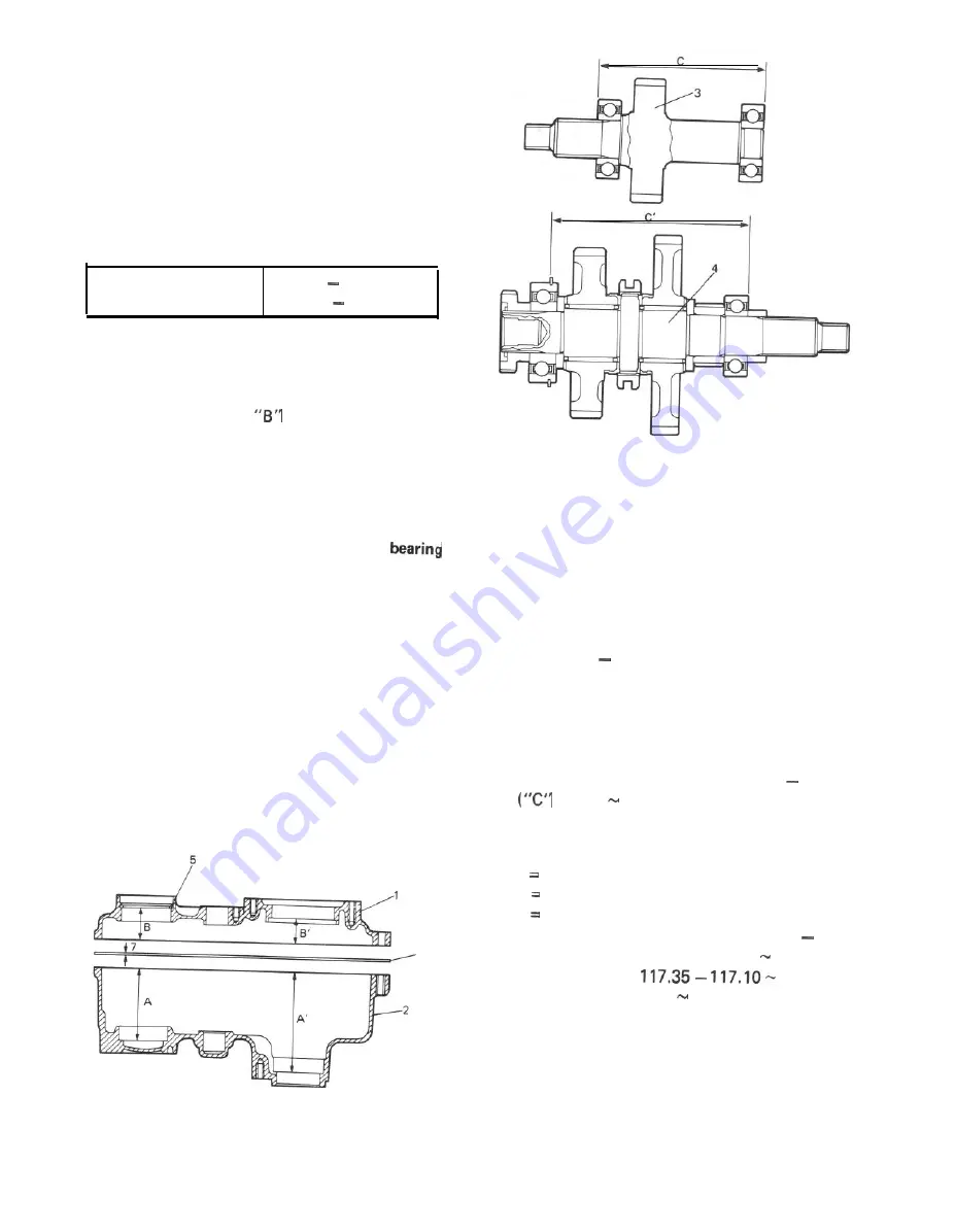
1) Take measurement “A” of rear case as shown
in figure below by using depth gauge,
2) Take measurement
of center case with
bearing circlip installed.
3) Take measurement
“C” (between bearing
inner races) of input shaft with bearings
installed, by using micrometer.
NOTE:
l
Before measuring, make sure that each
is free from abnormal noise or resistance by
spinning its outer race.
l
Each measurement in above steps 1) to 3)
must be taken accurately in careful manner,
If shim thickness is determined based on
rough measurement, clearance of each shaft in
thrust direction will not satisfy specification.
And improper clearance may cause oil leakage,
broken bearing and abnormal noise.
l
Take the same measurement at 3 to 4 diffe-
rent positions and use their mean.
6
1.
1. Center case
Center case
5.
5.
Bearing circlip
Bearing circlip
2.
2.
Rear case
Rear case
6.
6. Gasket
Gasket
3.
3.
Input shaft
Input shaft
7.
7. Gasket thickness
Gasket thickness
4. Output shaft
4. Output shaft
(0.3
mm or 0.012 in)
(0.3
mm or 0.012 in)
Fig.
Fig.
4) Using measurements obtained in steps 1) to 3)
and equation described below, calculate shim
thickness which is necessary for proper
thrust clearance.
Thrust clearance = (“A” + “B” + Gasket
thickness) “C”
As the above equation holds for thrust
clearance and gasket thickness is specified as
0.3 mm and thrust clearance as 0.05 to 0.15
mm, shim thickness is calculated by the
following equation.
Shim thickness = (“A” + “B” + 0.3 )
+ 0.05 0.15)
[Example]
Supposing A, B and C are as follows;
A 81.35 mm (3.203 in.)
B 35.70 mm (1.405 in.)
C 117.05 mm (4.608 in.)
Shim thickness = (81.35 + 35.70 + 0.3)
(117.05 + 0.05 0.15)
=
117.20
= 0.25 0.15
In this case, use of 0.15 to 0.25 mm (0.006 to
0.009 in) thick shim(s) will ensure specified
thrust clearance which is 0.05 to 0.15 mm
(0.002 to 0.006 in). Therefore 2 pieces of
0.1 mm (0.004 in) thick shim should be
selected in available shims below to satisfy
thickness.
14-16
Fig. 14-48-1
Содержание Samurai 1986
Страница 1: ......
Страница 9: ...0 9...
Страница 10: ...0 6...
Страница 11: ...0 7...
Страница 12: ...0 8...
Страница 13: ...0 9...
Страница 14: ...0 10...
Страница 15: ...0 11...
Страница 19: ...1 2...
Страница 20: ...1 3...
Страница 119: ...r a l I 29 Fig 4 1 1 Carburetor exploded view 4 3...
Страница 120: ...N Fig 4 l 2 Carburetor cross section 4 4...
Страница 154: ......
Страница 155: ...T c c x 5 5 3...
Страница 347: ...Fig 17 1 34 17 12...
Страница 348: ...17 13...
Страница 353: ...Fig 17 2 12 17 18...
Страница 354: ...17 19...
Страница 360: ...Fig 17 3 19 Fig 17 3 20 Fig 17 3 21 5 Fig 17 3 23 Ci Fig 17 3 24 Fig 17 3 22 17 25...
Страница 379: ...Steering Lower Shaft and Joint Universal joint rubber joint bolt Steering rubber ir Fig 18 31 11 0 18 0lb ft 18 15...
Страница 424: ...Fig 19 6 1 19 38 19 6 PARKING BRAKE...
Страница 448: ...20 13...
Страница 450: ...21 2...
Страница 475: ...22 5...
Страница 476: ...22 6...
Страница 477: ...22 7...
Страница 478: ...22 8...
Страница 479: ...22 9...
Страница 480: ......
Страница 481: ......
Страница 482: ...Prepared by SUZUKI MOTOR CO LTD Technical Department Automobile Service Division 1st Ed November 1987 Printed in Japan...


