21
5. Couple the tractor to the transportation hitch bar. To do so you must release the
butterfly nut A in figure 5, this allows to lower the bar for its hook up.
6. CAUTION!!! Before moving the planter, control that the wheels that have turning locks
are not locked down. These are the two rear wheels, taking as a reference the
transportation position and the moving direction of the planter. To unlock them, you
must remove the turning locks, pulling upwards and placing them in the surface A
figure 8. You many need to move or turn slightly the wheel to accomplish this.
7. In these conditions, you will need to move forward very slowly with the tractor in a
straight line. The wheels will start to align by themselves in a transportation direction.
Release the two turning locks from their surface A in figure 8 and control and assure
that they are pinned down in the hole, in this way locking the wheel from turning
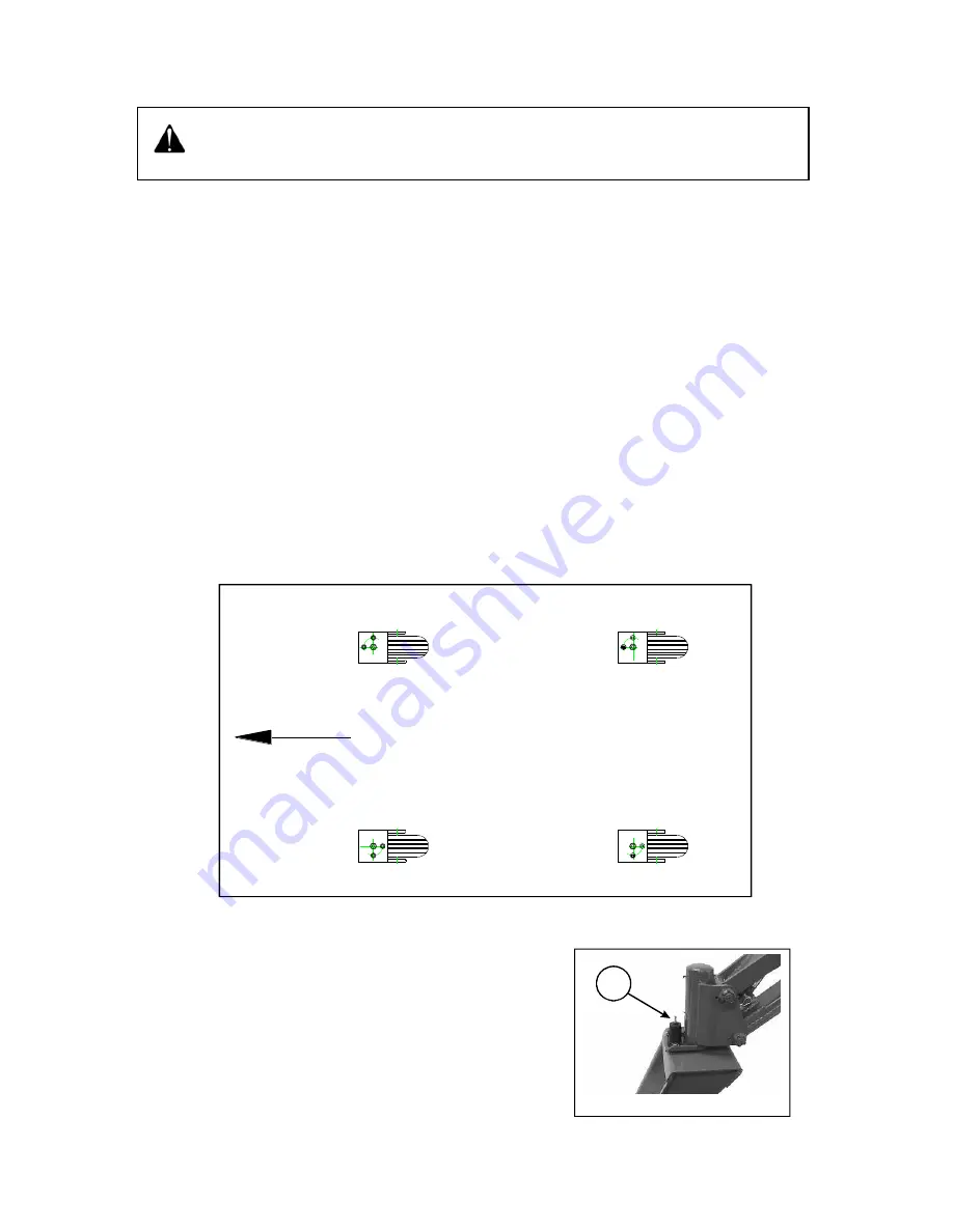
again. Locking all the wheels may require several tractor movements, once ready all
the wheels must look as in figure 11.
8. Also regulate the pressure of the turning brake in the two front wheels.
Adjusting or loosening the square head set screw shown as
A in figure 12, the turning resistance is reduced or
increased, this affects the planter´s maneuverability and
stability while transporting.
Once all of these steps have been performed the planter is
ready for its transportation.
Figure 12
Make sure that the planter will not move during this operation, when releasing the work
hitch bar. Chock the wheels, lock them, and perform this in a leveled, plain terrain, NEVER
IN UNEVEN SURFACES.
With turning brake
With turning lock
With turning lock
With turning brake
TRANSPORTATION
DIRECTION
A
Figure 11
Содержание W630
Страница 1: ...OPERATOR S MANUAL W 630...
Страница 2: ...2...
Страница 4: ...4...
Страница 6: ...6...
Страница 8: ...8...
Страница 60: ...60 This page intentionally let blank...
Страница 64: ...64 This page intentionally let blank...
Страница 66: ...66...


