15
742.110 | 14.50
EN
6
Structure
6.1
Casing
11
13
2
16
15
14
ESC
SET
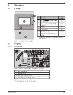
No. Element
see
section
Mode
button (under
front panel)
7.1
8
,
SET
,
ESC
,
operating
buttons
7.1
Display
6.2
Front panel
4.1
Terminal cover
4.3.1
1)
Terminal cover fastening
screw
–
1)
Section 4.3.1 describes the terminals under the
terminal cover.
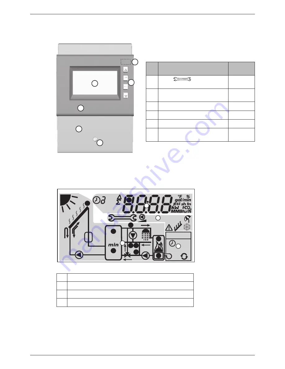
Fig. 7: Front view of the controller
6.2
Display
6.2.1
Overview
~
~~
~
~
max
min
max
T
T
T
T
T
V
T
T
T
S
yst
F
unc
P
ara
SET
h
Interv.
min
max
on
off
T
4
1
3
2
Fig. 8: Overview of the display areas (all elements visible)
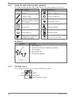
System graphics
Settings menu
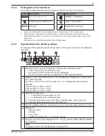
Pictograms for functions
Operational and setting values
The display areas are described below.
Содержание TR-A501T-U
Страница 47: ...47 742 110 14 50 EN 18 Notes ...
Страница 48: ...48 742 110 14 50 EN 742110 ...


