17
742.110 | 14.50
EN
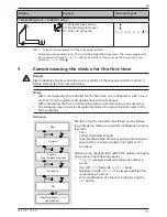
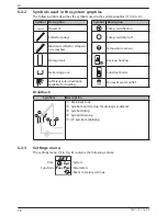
6.2.4
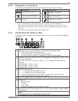
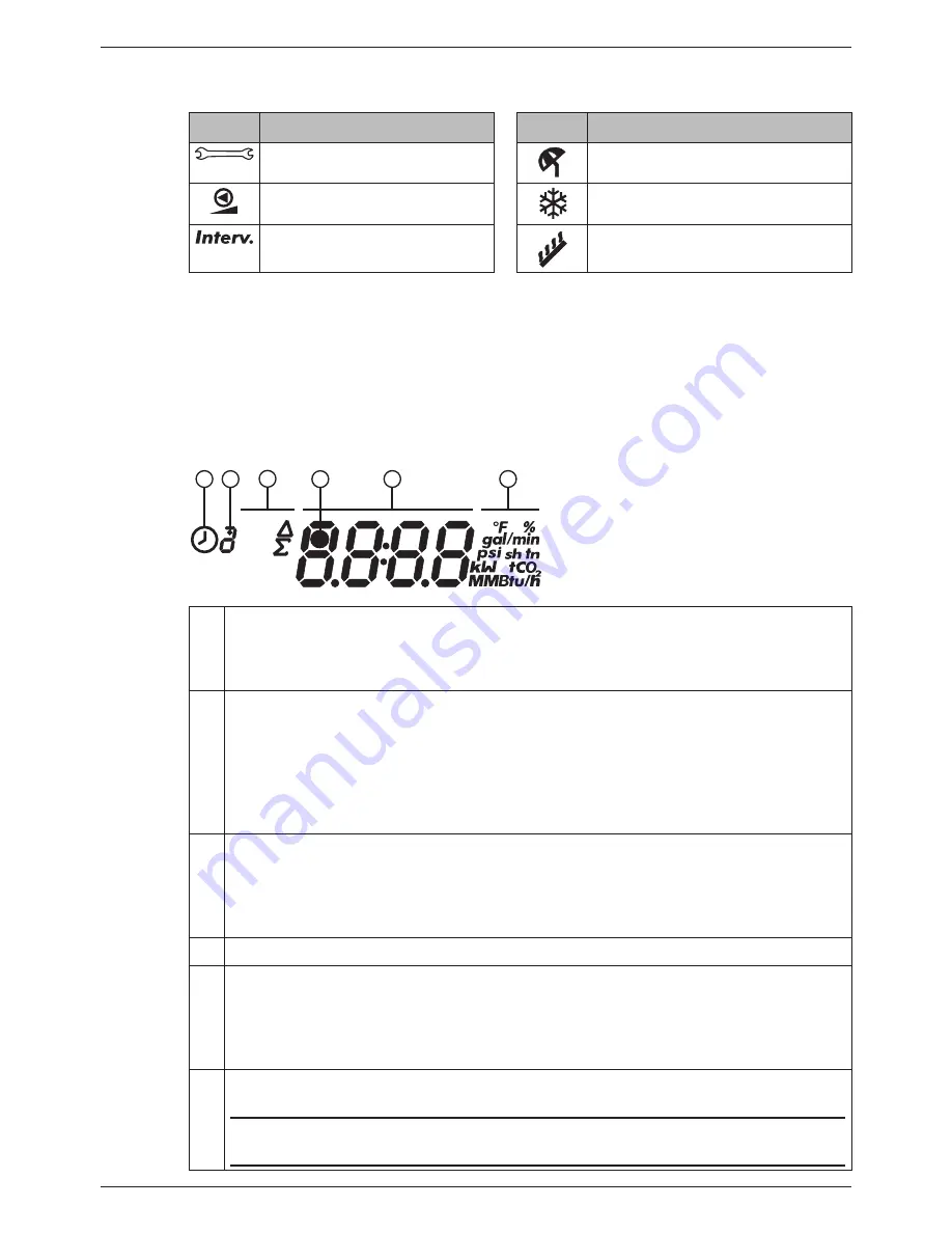
Pictograms for functions
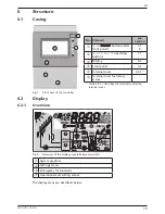
The following table describes the pictograms used for functions (
in Fig. 8).
Symbol Description
Symbol Description
Manual
operation
Holiday – recooling
2)
Pump is speed controlled
1)
Freeze recirculation
2)
Interval
2)
Stagnation reduction
2)
1)
Symbol is visible while the function/parameter is being edited in the settings menu.
2)
Symbol flashes: The function is activated and is actively intervening in the control process.
Symbol
does not
flash: The function is activated and is
not
actively intervening in the control
process
or
the function is currently being edited in the setting menu.
6.2.5
Operational and setting values
The display of the operational and setting values (
in Fig. 8) consists of the following
elements:
h
1 2
3
5
6
4
min
max
on
off
T
Symbol for time control of functions. This symbol is displayed when
•
a time restriction/control has been set,
•
the status of time restriction/control is displayed,
•
the time restriction blocks a temperature control (symbol flashes).
Number of the time window that is currently being set/displayed or within which
the current time lies.
The time control of a function consists of 1 to 3 configurable time windows.
Example:
Time window 1: 06:00 – 08:00
Time window 2: 11:00 – 12:30
Time window 3: 17:00 – 19:00
Additional information:
on
,
off
: Switching state/condition
on
,
off
max
,
min
:
Maximum
value,
minimum
value
Σ:
Summed operational value since first commissioning, cannot be reset
Δ:
Summed
operational value since last reset to 0
Symbol is displayed when a temperature sensor is selected when setting a function.
Display of:
•
Measurements
•
Settings
•
Error codes
•
Additional information, e.g. software version
Physical unit of the value displayed in
: °F, F, psi, gal/min, MBtu, MBtu/h, MMBtu,
%, tn sh CO
2
Note
The physical units are only displayed as appropriate.
Содержание TR-A501T-U
Страница 47: ...47 742 110 14 50 EN 18 Notes ...
Страница 48: ...48 742 110 14 50 EN 742110 ...


