background image

23

742.110 | 14.50

EN

9.3 

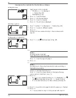
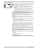
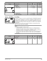
Setting the time


Note

The time must be once more set to the correct values if power is removed for

a longer period of time. After this, the same operating mode is displayed as was active

previous to the removal of power.


 flashes.

1.  Press 

SET

. The hours display flashes. 

2.  Press 



 to change the hour.

3.  Press 

SET

. The minute flashes. 

4.  Press 



 to change the minute.

5.  Press 

SET

. The change is adopted.

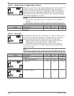
9.4 

Setting the system


Note

The systems are described in section 4.4, p. 10.


S

yst

 flashes.

1.  Press 

SET

. The number of the current system flashes.

2.  Press 



 to select a different system. 

3.  Press 

SET

. The change is adopted. 

9.5 

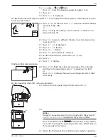
Setting the functions 


F

unc

 flashes.


X

Continue as described in section 10. 

9.6 

Setting the parameters 


Note

Details on the parameters are provided in section 11, p. 39.


P

ara

 flashes.

1.  Press 

SET

P:01

 (Parameter number) flashes.

2.  Press 



 to display a different parameter.

3.  Press 

SET

. The value of the parameter is displayed, associated components flash in 

the system graphics.

4.  Press 

SET

. The parameter value flashes.

5.  Press 



 to change the value.

6.  Press 

SET

 to adopt the change.

7.  Press 

ESC

. The parameter number is displayed (flashing).

8.  If necessary, repeat steps 2 – 7.

9.7 

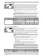
Resetting to factory settings


 flashes, 

RESEt

 is displayed (

RE

 and 

SEt

 alternately).

1.  Press and hold 

SET

 for 5 seconds. 

2.  A progress display is shown for a few seconds. After this the reset is finished.
3.  Continue as described in section 5, p. 11.

Содержание TR-A501T-U

Страница 1: ...Temperature differential controller 5 inputs 1 output 742 110 Z03 14 50 Subject to change due to technical improvements EN Installation and operating instructions ...

Страница 2: ...ure 15 6 1 Casing 15 6 2 Display 15 7 Operation 18 7 1 Operating buttons 18 7 2 Display when operating 18 8 Modes of operation 18 8 1 Changing the mode of operation 18 8 2 Off mode 19 8 3 Manual mode 19 8 4 Automatic mode 20 9 Settings menu 22 9 1 Overview 22 9 2 Calling up the settings menu and selecting a menu entry 22 9 3 Setting the time 23 9 4 Setting the system 23 9 5 Setting the functions 2...

Страница 3: ...wer supply when the casing is open or damaged cables are damaged Factory labels and markings must never be altered removed or rendered unreadable Observe the prescribed conditions of use see section 15 p 45 This device is not intended for Children Persons with physical sensory or mental impairment Persons without sufficient experience or knowledge unless they are instructed in the use of the devic...

Страница 4: ...ssary training knowledge and experience and knowledge of the ap plicable regulations in order to evaluate and recognise the dangers inherent in the following work Installation of electrical equipment Production and connection of data communication cables Production and connection of mains grid power supply cables 3 3 Danger levels in warning notices Évaluation du niveau de risque dans les avertiss...

Страница 5: ...rds Fig 1 Fig 1 Removing the front panel 4 1 2 Mount the front panel X Carefully position the front panel and then press it onto the casing until it latches into place 4 1 3 Remove the terminal cover Danger Risk of death by electrocution Disconnect the controller from the power supply before removing the terminal cover Make sure that the power supply cannot be unintentionally switched on when the ...

Страница 6: ...he terminal cover 2 Screw in the screw for the upper mounting hole Fig 2 until the screw head has a clearance of 5 7 mm 0 20 0 28 inch from the mounting surface 3 Hang the controller on the screw by the upper mounting hole and align it vertically 4 Mark the position of the lower mounting hole through the casing 5 Remove the controller and prepare the mounting hole for the lower screw 6 Hang the co...

Страница 7: ...nnected to the mains power as follows using a plug connected to a wall mains socket or via an isolating mechanism allowing complete isolation in the case of permanent wiring The power supply cable must be laid in conformance to all applicable legal guide lines and regulations of the local electricity supplier Notice Danger of damage and malfunction Connect only components that do not overload the ...

Страница 8: ...nductor terminal block PE 4x protective earth common protective earth for power connection terminal block Signals terminal block 1 4 4x sensor input Pt1000 temperature sensor 5 1x sensor input Pt1000 temperature sensor or pulse water meter input RS not used 0 10 R1 1x control output for 0 10 V controlled high efficiency pumps 6x mass connection common mass for sensor inputs and control out puts Pi...

Страница 9: ...ls as described in sec tion 4 4 p 10 Mains input and output First connect PE then N and L Strain relief First clamp the lower strain relief clamps and then the upper strain relief clamps When using the upper strain relief clamps use the plastic links as described below If the opening in the strain relief clamp is too large e g in the case of thin ca bles turn over the strain relief clamping bar wi...

Страница 10: ...valves temperature sensors must be connected to particular terminals The following table provides information on this Graphic and number of the solar system on the controller display The graphic is only intended to provide an overview and is not a technical drawing Terminal pin assignments of the connected components Display Legend Terminal layout No system Note No System is used when only the fun...

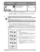
Страница 11: ...h a man ner that it can be used in most applications without changes After completing the first commissioning later recommissioning is not necessary The following steps must also be performed after the device has been reset to the factory settings Overview Time System Pump R1 Type minimum speed Functions ESC ESC ESC Operation mode Off is switched on ESC OK SET The first time the controller is swit...

Страница 12: ...8 Setting pump 1 output R1 9 Press AC and flash example in Fig left 10 Notice Standard pump Select AC High efficiency pump Select HE Press to set the type of pump 1 11 Press SET 12 Notice Pay attention to the pump characteristics when selecting HE high efficiency pump Only if HE was selected in step 10 Press to set the characteristics of the high efficiency pump see Tab 2 and Fig 6 on p 14 13 Pres...

Страница 13: ...ess SET The function is activated 25 Set the characteristics see section 10 1 p 25 26 Press ESC 27 Press Ok flashes Finishing Initial commissioning 28 Press SET to finish the initial commissioning The controller switches to the operating mode Off example in Fig left or Press ESC to display the previous settings and correct them if necessary Set the operating mode off manual automatic 29 Remove the...

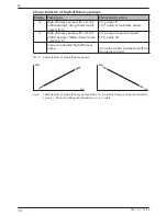
Страница 14: ...fficiency pump with a 0 10 V profile having a falling characteristic curve Fig 6 0 V pump at maximum speed 10 V pump off C Pressure controlled high efficiency pump no control cable switched on off via the supply voltage Tab 2 Characteristics of high efficiency pumps U V RPM U V RPM Fig 6 Characteristics of high efficiency pumps with a 0 10 V profile having a rising characteristic curve bA left and...

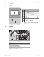
Страница 15: ...minal cover fastening screw 1 Section 4 3 1 describes the terminals under the terminal cover Fig 7 Front view of the controller 6 2 Display 6 2 1 Overview max min max T T T T T V T T T Syst Func Para SET h Interv min max on off T 4 1 3 2 Fig 8 Overview of the display areas all elements visible System graphics Settings menu Pictograms for functions Operational and setting values The display areas a...

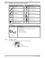
Страница 16: ...ure reached Temperature sensor Storage tank Back up heating Swimming pool Solid fuel boiler Sufficient solar irradiation available for loading Domestic water outlet Drainback Symbols Description 1 2 3 4 Drainback tank Symbol Short startup for drainage assistance Symbol Filling Symbol Draining Symbol Stabilising 6 2 3 Settings menu The settings menu in Fig 8 contains the following entries Syst Func...

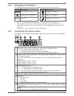
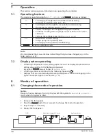
Страница 17: ...me control of functions This symbol is displayed when a time restriction control has been set the status of time restriction control is displayed the time restriction blocks a temperature control symbol flashes Number of the time window that is currently being set displayed or within which the current time lies The time control of a function consists of 1 to 3 configurable time windows Example Tim...

Страница 18: ...he operating mode Note We recommend that you write down all settings that you have changed e g in the Notes section p 47 7 2 Display when operating A flashing component in the system graphic means The displayed operational or setting value applies to the flashing component Exception always flashes in manual mode A flashing symbol is indicated in the following figures by Displays that are automatic...

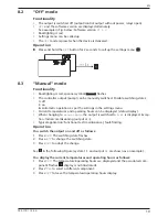
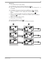
Страница 19: ...ttings in the settings menu Current temperatures and operating hours can be displayed status display When changing to manual mode the output is switched to A R1 is displayed Excep tion Initial commissioning output at 0 Typical application Functional test maintenance fault finding Operation You switch the output on and off as follows 1 Press SET The switching state flashes 2 Press to change the swi...

Страница 20: ...s of external components tempera tures switching states run times Display stored min max values temperature sensors or sum difference values op erating hours1 of the pumps and valves Summed values symbol Operating hours since first commissioning Summed values cannot be reset Difference values symbol Δ Operating hours since the last reset to 0 Reset the stored min max difference values Call up the ...

Страница 21: ...s 1 Press as required in order to display other components component flashes 2 Press SET The min max difference values are displayed alternately 3 If desired press and hold the SET button for 2 seconds to reset the currently displayed value 4 Press ESC The status display is shown 5 Repeat steps 1 to 4 if necessary You access the settings menu as follows X Press and hold SET for 2 seconds The setti...

Страница 22: ... Depending on the system selected only certain functions and parameters can be accessed Quick charge F05 Freeze recircula tion F06 Maximum temperature storage tank P01 Maximum collector temperature P05 Minimum collector temperature P06 Loading strategy P07 Switch on temperature difference solar circuit P03 Reset to factory settings 1 storage tank 1 collector array 1 1 Holiday recooling F02 Maximum...

Страница 23: ...ge is adopted 9 5 Setting the functions Func flashes X Continue as described in section 10 9 6 Setting the parameters Note Details on the parameters are provided in section 11 p 39 Para flashes 1 Press SET P 01 Parameter number flashes 2 Press to display a different parameter 3 Press SET The value of the parameter is displayed associated components flash in the system graphics 4 Press SET The para...

Страница 24: ...ows Func flashes 1 Press SET F 01 flashes 2 Press to display the next function Activating the function A function must be activated activation on Fig left and all the associated characteristics must be correctly set before it can be used If a function is activated and then exited before the character istics are set then oFF flashes briefly After this the function is displayed with a switching stat...

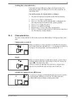
Страница 25: ... function number flashes 10 2 Characteristics The main characteristics for the functions are described below The figures show exam ples Temperature control When a function is to be temperature controlled the tempera ture control must be switched on tc temperature control In the figure the temperature control is switched off off Input When a function requires a temperature sensor a sensor input mus...

Страница 26: ...g performed Switch off temperature If a function contains a thermostat then the switch off tempera ture can be set The affected sensor symbol blinks while settings are being performed Time control If a function is to be time controlled then the time control must be activated and the time windows must be set cc clock control In the Fig at the left the time control is switched off off Starting time ...

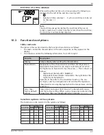
Страница 27: ...haracteristics and their interdependence Dependent characteristics can only be selected and set when the higher level characteristic has the value on This is shown as follows Higher level characteristic bold text Dependent characteristics indented to the right below the higher level characteristic Example In the table for the circulation function the sen sor input switch on temperature and switch ...

Страница 28: ...abilising time The fol lowing applies The solar circuit pump also continues to run for this time even when the switch off conditions are satisfied When the speed control is activated and the solar irradiation is too low no sun symbol on the display the pump runs at minimum speed After expiry of the stabilising time the controller checks to see if the solar irradiation is sufficient to continue loa...

Страница 29: ...the stor age tank temperature during the day was 20 F below the set maximum temperature Stagnation occurs when not enough hot water is removed from the system during an absence holiday Notes The following applies to this function Only activate if you intend to be absent for an extended period Deactivate this after returning from a holiday in order to avoid an unnecessary waste of energy via the co...

Страница 30: ...haracteristic min max Factory setting Activation on oFF oFF 10 3 4 Interval Periodically switches the solar circuit pump on and off in order to meas ure the actual collector temperature The delay between 2 switch on operations and the switch on duration can be set Applications Collector types where the mechanical construction prevents the temperature from being measured at a suitable place Unsuita...

Страница 31: ... Switch off temperature Toff Ton 4 F Ton 20 F 130 F 10 3 6 Freeze recirculation Attempts to prevent freezing of the collectors by pumping heat from the storage tank into the collectors Collector temperature below 40 F solar circuit pump is switched on Collector temperature above 45 F solar circuit pump is switched off The freeze recirculation function is only useful when the heat transfer fluid co...

Страница 32: ...m System 0 1 has been selected Glycol proportion and accounting for the temperature dependent thermophysical properties of the heat transfer fluid Additional possibility Display of the amount of CO2 saved by using the system The amount of CO2 is calculated from the acquired heat volume To do this the controller requires the conversion factor IbsCO2 kWhtherm to be entered Display Characteristic min...

Страница 33: ...awaiian Electric Co Inc HECO Residential Rebate Program Solar water heating system information sheet 2007 1 918 IbsCO2 kWhtherm 10 3 9 Circulation Switches a circulation pump on and off on a temperature and or time controlled basis The pump must be connected to output R1 Temperature control If the temperature in the circulation return falls below the Ton value then the circulation pump is switched...

Страница 34: ...e tank using an oil or gas burner The function can be time restricted Temperature control If the temperature in the storage tank falls below the Ton value then the external heating is switched on until the Toff tem perature is reached Time restriction The function is executed when the current time lies within one of 3 configurable time windows Display Characteristic min max Factory setting Activat...

Страница 35: ...l boiler temperature The storage tank temperature reaches the max storage tank tem perature Speed control of the pump can be activated as required The loading strategy of the speed control system attempts to regulate the tempera ture of the solid fuel boiler to match the control target that has been set The control target should be at least 20 F above the minimum tempera ture of the solid fuel boi...

Страница 36: ...ivation on oFF oFF Sensor input for storage tank temperature 1 5 Sensor input for heating return increase temperature 1 5 Switch on temperature difference Tdiff on Tdiff off 4 F 100 F 12 F Switch off temperature difference Tdiff off 0 F Tdiff on 4 F 6 F 10 3 13 Thermostat T Func SET on Switches output R1 on and off depending on the temperature range of any desired sensor The function can be time r...

Страница 37: ...difference drops below Tdiff off In addition to this the discharging of the heating source can be limited to a particular temperature range Tsrc min Tsrc max and the loading of the heating target can be limited to a maximum value Tsink max Time restriction The function is executed when the current time lies within one of 3 configurable time windows Speed control of the pump can be activated as req...

Страница 38: ...ET C max Heat sink max temperature Tsink max 32 F 200 F 140 F Time restriction on oFF oFF Time window 1 start end Time window 2 start end Time window 3 start end 0 00 0 00 0 00 23 59 23 59 23 59 00 00 00 00 00 00 00 00 00 00 00 00 1 Notice Standard pump Set AC High efficiency pump Set HE 2 Notice External consumer e g 115 V relay Set AC pump type and set the speed control to oFF ...

Страница 39: ... perature drops to 6 F below the set value T Para SET max Maximum tempera ture swimming pool 50 F 115 F 85 F When the maximum tem perature is exceeded no more loading occurs until the tem perature drops to 1 F below the set value T T Para SET on Switch on tempera ture difference solar circuit TP04 4 F 100 F 16 F When the switch on tem perature difference between collector and storage tank is reach...

Страница 40: ...rature loading dIFF 4 F 100 F 16 F Control target of absolute temperature loading AbS 32 F 200 F 140 F Para SET R1 pump type AC HE AC Notice Danger of malfunctions in the controller or damage to the components With a high efficiency pump HE must be set and with a standard pump AC must be set Set speed control to oFF when an external relay is con nected or speed control is not wanted Pump character...

Страница 41: ...The maximum collector temperature has been reached the solar circuit pump in the respective solar circuit has been switched off The symbols in the status display flash when the tempera ture of the respective collector is selected T The maximum collector temperature has been reached the solar circuit pump in the respective solar circuit has been switched off is shown in the status display when the ...

Страница 42: ...er not functioning at all Display empty dark Controller power supply is interrupted Check the controller power cable Check the fuse for the power supply Controller constantly displays 12 00 12 flashes Controller power supply was interrupted for longer than 15 minutes Set the time Solar circuit pump not operating switch on condition is fulfilled Pump power supply is interrupted Check the pump power...

Страница 43: ...o small Adjust temperature difference in the Parameters settings menu Collector sensor incorrectly positioned Check the position of the collector sensor and correct if necessary Tab 5 General faults 14 2 Error messages When an error message is displayed the backlighting turns red and starts flashing if no button has been pressed for 5 minutes The systems shown in the following error messages are o...

Страница 44: ...ensors Danger Risk of death by electrocution Before opening the device make sure that all cables leading to the device have been disconnected from the mains power and cannot be unintentionally reconnected to the mains power 1 Remove the terminal cover 2 Disconnect the temperature sensor 3 Measure the resistance of the temperature sensor with an ohmmeter and compare with Tab 7 Small deviations are ...

Страница 45: ... pulse 10 l pulse 25 l pulse flow rate acquisition Signal output 0 10 R1 Type Min working resistance 0 10 V 10 kΩ Hydraulic schemes systems Quantity 2 Display Type LCD display with backlighting Application conditions Degree of protection IP22 DIN 40050 without front panel IP20 Protection class I Ambient temperature 32 122 F when wall mounted Physical specifications Dimensions L x W x H 110 x 160 x...

Страница 46: ...guarantee In accordance with German statutory regulations there is a 2 year legal guarantee on this product for the customer The seller will remove all manufacturing and material faults that occur in the product during the guarantee period and affect the correct functioning of the product Natural wear and tear does not constitute a malfunction No legal guarantee can be offered if the fault can be ...

Страница 47: ...47 742 110 14 50 EN 18 Notes ...

Страница 48: ...48 742 110 14 50 EN 742110 ...

Отзывы: